

LIBRARY ı6ıul 0) - Cranfield University
LIBRARY ı6ıul 0) - Cranfield University
LIBRARY ı6ıul 0) - Cranfield University

Create successful ePaper yourself
Turn your PDF publications into a flip-book with our unique Google optimized e-Paper software.
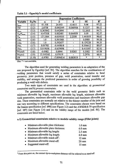
Table 3.1 - Ogunbiyi's model coefficients<br />
Regression Coefficients<br />
Variable E . No a S SE R2<br />
'mean (3.1) 61.318 24.053<br />
-0.4611<br />
9.98 97.22<br />
TSI (3.2) 2.8758<br />
-0.002549 -0.060936<br />
0.1237 88.12<br />
Imean (3.3) 0.363842 0.642844<br />
-<br />
12.2015 99.71<br />
VbkVmean (3.4)<br />
-0.47318<br />
0.002481 0.044959 0.09 92.57<br />
Vbk (3.5) -27.3364 -0.039555<br />
2.2558 1.441019 98.62<br />
Leg, (3.6) 1.0 0.561068<br />
-<br />
0.0980 99.58<br />
Leb (3.6) 1.0 0.592637<br />
-<br />
0.129228 99.35<br />
Pen, (3.7) 0.01782<br />
-0.449818 -<br />
0.356612 89.07<br />
Penb (3.7) 0.019058 -0.639698 -<br />
0.415507 82.92<br />
Pr(und) (3.8) -0.0982<br />
0.0044 0.0265 0.3502 65.98<br />
Pr(arc) (3.9) 13.519345 0.97619<br />
-<br />
2.2976 48.61<br />
PR (3.10) -0.9785 -7.0094E-6 0.083019<br />
Obs: *= not available.<br />
The algorithm used for generating welding parameters is an adaptation of the<br />
one proposed by Ogunbiyi [ref. 51]. The algorithm searches for the combinations of<br />
welding parameters that would satisfy a series of constraints relative to bead<br />
geometry, joint position, presence of gap, weld penetration, metal transfer and<br />
stability, and arranges the predicted parameters in order of growing possibility of<br />
producing a weld with defects.<br />
Two main types of constraints are used in the algorithm: a) geometrical<br />
constraints and b) process constraints.<br />
The geometrical constraints refer to the weld geometry limits such as<br />
minimum allowable leg length, maximum allowable leg length, minimum allowable<br />
weld penetration, maximum allowable weld penetration and maximum allowable gap<br />
size. These constraints are normally set relative to the thinner member of the joint and<br />
can vary according to different specifications. The constraints chosen were based on<br />
the Inauxa specification [ref. 190] (see Figure 3.3) and the AWSD8: 8-79 specification<br />
[ref. 107] (see Figure 3.4) and on the validity range of the models [ref. 51]. The<br />
constraints are listed below.<br />
a. 1) Geometrical constraints relative to models validity range (Fillet joints)<br />
" Minimum allowable plate thickness: 1.0 mm<br />
" Maximum allowable plate thickness: 6.0 mm<br />
" Minimum allowable leg length: 2.5 mm<br />
" Maximum allowable leg length: 6.0 nun<br />
" Minimum allowable stand-off: 12 mm<br />
" Maximum allowable stand-off: 20 mm<br />
" Suggested stand-of 15 mm<br />
5 From this point on, the contact tip-to-workpiece distance will be referred to as stand-off<br />
71


