

LIBRARY ı6ıul 0) - Cranfield University
LIBRARY ı6ıul 0) - Cranfield University
LIBRARY ı6ıul 0) - Cranfield University

Create successful ePaper yourself
Turn your PDF publications into a flip-book with our unique Google optimized e-Paper software.
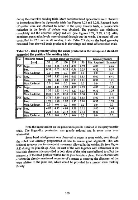
during the controlled welding trials. More consistent bead appearances<br />
were observed<br />
to be produced from the dip transfer trials (see Figures 7.23 and 7.25). Reduced levels<br />
of spatter were also observed to occur. In the spray transfer trials, a considerable<br />
reduction in the levels of defects was obtained. The porosity was eliminated<br />
completely and the undercut largely reduced (see Figures 7.27,7.29,7.31). Also,<br />
consistent penetration levels were obtained through-out the welds. The stand-off was<br />
controlled to ±2.5 mm in all welding trials. Table 7.5 shows the bead geometry<br />
measured from the weld beads produced in the voltage and stand-off controlled trials.<br />
Table 7.5 - Bead geometry along the welds produced in the voltage and stand-off<br />
controlled flat position fillet welding trials<br />
Run Measured feature Position alon the weld mm Geometry feature<br />
mm 30 65 100 135 170 Min. R uired Expected<br />
SV2 4.85 4.56 4.58 4.78 4.59 4.00 4.46<br />
Pen,, 0.58 0.63 0.53 0.56 0.55 0.32 0.57<br />
Max. Undercut 0.0 0.0 0.0 0.0 0.0 0.0 0.0<br />
SV3 Le 5.95 5.87 5.91 6.03 5.83 6.00 6.41<br />
peng 1.00 1.14 1.07 0.93 1.01 0.32 1.21<br />
Max. Undercut 0.0 0.0 0.0 0.0 0.0 0.0 0.0<br />
SW Le 4.08 4.11 3.98 4.07 4.19 4.00 4.54<br />
Pen., 1.32 1.25 1.40 1.27 1.33 0.32 1.26<br />
Max. Undercut 0.37 0.25 0.37 0.32 0.30 0.0 0.0<br />
SV5 Le 5.73 5.39 5.55 5.63 5.53 5.00 5.40<br />
Pen., 1.70 1.90 1.92 1.85 2.08 0.32 1.70<br />
Max. Undercut 0.0 0.0 0.0 0.0 0.0 0.0 0.0<br />
SV6 Le 4.82 4.73 4.99 5.21 5.12 5.00 5.43<br />
Pen., 2.22 2.31 2.12 2.20 2.14 0.32 1.86<br />
Max. Undercut 0.0 0.0 0.0 0.0 0.0 0.0 0.0<br />
Note the improvement on the penetration profile obtained in the spray transfer<br />
trials. The finger-like penetration was greatly reduced and in some cases even<br />
eliminated.<br />
Some bead misalignment was observed to occur in some welds, even though<br />
the robot was carefully programmed on-line to ensure good alignment. This was<br />
believed to occur due to some joint movement allowed in the welding jig (see Figure<br />
5.1) during the joint fit-up. Also, the cast of the wire together with differences in the<br />
heat sink characteristics provided in both sides of the joint were believed to affect the<br />
symmetry of the bead profiles relative to the joint bisection plane. These observations<br />
confirm the already mentioned necessity of a means to ensuring the alignment of the<br />
wire relative to the joint line, which could be provided by a proper seam tracking<br />
facility.<br />
169


