

LIBRARY ı6ıul 0) - Cranfield University
LIBRARY ı6ıul 0) - Cranfield University
LIBRARY ı6ıul 0) - Cranfield University

You also want an ePaper? Increase the reach of your titles
YUMPU automatically turns print PDFs into web optimized ePapers that Google loves.
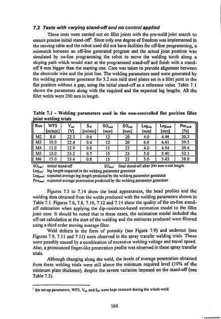
7.2 Tests with varying stand-off and no control applied<br />
These tests were carried out on fillet joints with the pre-weld joint search to<br />
ensure precise initial stand-of e. Since only one degree of freedom was implemented in<br />
the moving table and the robot used did not have facilities for off-line programming, a<br />
mismatch between an off-line generated program and the actual joint position was<br />
simulated by on-line programming the robot to move the welding torch along a<br />
sloping path which would start at the programmed stand-off and finish with a stand-<br />
off 8 mm bigger than the starting one. Care was taken to provide alignment between<br />
the electrode wire and the joint line. The welding parameters used were generated by<br />
the welding parameter generator for 3.2 mm mild steel plates set in a fillet joint in the<br />
flat position without a gap, using the initial stand-off as a reference value. Table 7.1<br />
shows the parameters along with the required and the expected leg lengths. All the<br />
fillet welds were 200 mm in length.<br />
Table 7.1 - Welding parameters used in the non-controlled flat position fillet<br />
joint welding trials<br />
Run WFS<br />
ril/min<br />
V. 4<br />
Sw<br />
H1/mm<br />
SO,,.,,<br />
mm<br />
SO.. d<br />
mm<br />
LeS,<br />
ea<br />
trim<br />
Legpmd<br />
Imml<br />
M2 8.0 22.1 0.6 12 20 4.0 4.46 30.3<br />
M3 10.0 22.4 0.4 12 20 6.0 6.41 39.5<br />
M4 11.0 32.9 0.8 15 23 4.0 4.54 39.4<br />
M5 13.0 33.2 0.7 15 23 5.0 5.40 53.1<br />
M6 15.0 33.4 0.8 15 23 5.0 5.43 58.0<br />
SO,,.,: initial stand-off<br />
SOci, d: final stand-off after 200 mm weld length<br />
Leggy: leg length required in the welding parameter generator<br />
Leggy: expected average leg length predicted by the welding parameter generator<br />
Pence: expected average penetration predicted by the welding parameter generator<br />
Pen<br />
10/01<br />
Figures 7.5 to 7.14 show the bead appearances, the bead profiles and the<br />
welding data obtained from the welds produced with the welding parameters shown in<br />
Table 7.1. Figures 7.6,7.8,7.10,7.12 and 7.14 show the quality of the on-line standoff<br />
estimation when applying the dip-resistance-based estimation model to the fillet<br />
joint case. It should be noted that in these cases, the estimation model included the<br />
off-set calculation at the start of the welding and the estimates produced were filtered<br />
using a third order moving average filter.<br />
Weld defects in the form of porosity (see Figure 7.9) and undercut (see<br />
Figures 7.9,7.11 and 7.13) were observed in the spray transfer welding trials. These<br />
were possibly caused by a combination of excessive welding voltage and travel speed.<br />
Also, a pronounced finger-like penetration profile was observed in these spray transfer<br />
trials.<br />
Although changing along the weld, the levels of average penetration obtained<br />
from these welding trials were still above the minimum required level (10% of the<br />
minimum plate thickness), despite the severe variation imposed on the stand-off (see<br />
Table 7.2).<br />
1 the set-up parameters, WFS, V.. and Sw were kept constant during the whole weld.<br />
166


