

LIBRARY ı6ıul 0) - Cranfield University
LIBRARY ı6ıul 0) - Cranfield University
LIBRARY ı6ıul 0) - Cranfield University

Create successful ePaper yourself
Turn your PDF publications into a flip-book with our unique Google optimized e-Paper software.
centre. This is attributed to the more uniform heat input and arc pressure distribution<br />
over the weld pool, provided by the high speed rotation. Effects on the wire bum-off<br />
were also observed in this process. The high speed rotation of the arc induces<br />
centrifugal forces to act on the droplets at the tip of the wire, affecting the droplet<br />
transfer phenomenon [ref. 135]. Dominant forces on the droplets at the wire tip are<br />
magnetic pinch force, detachment force, rotation centrifugal force, and interfacial<br />
force. An increase in rotation speed results in increased centrifugal force, which<br />
induces the droplets to become smaller and the transfer cycle to become shorter.<br />
Correspondingly, the extent of overheating by arc heat reduces and the heat retained<br />
in the droplets (droplet temperature) decreases, resulting in an increased wire bum-off<br />
[refs. 134,135].<br />
rate<br />
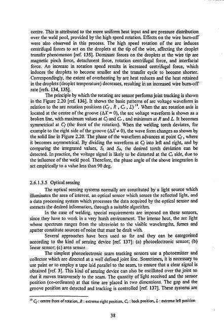
The principle by which the rotating arc sensor performs joint tracking is shown<br />
in the Figure 2.20 [ref. 136]. It shows the basic patterns of arc voltage waveform in<br />
relation to the arc rotation positions (Cf, R, C, , L) 19. When the arc rotation axis is<br />
located at the centre of the groove (OX = 0), the arc voltage waveform is shown as a<br />
broken line, with maximum values at Cf and C, , and minimum at R and L. It becomes<br />
symmetrical at Cf (the front of the rotation). When the welding torch deviates, for<br />
example to the right side of the groove (AX # 0), the wave form changes as shown by<br />
the solid line in Figure 2.20. The phase of the waveform advances at point Cf, where<br />
it becomes asymmetrical. By dividing the waveform at Cf into left and right, and by<br />
comparing the integrated values, SL and SR, the desired torch deviation can be<br />
detected. In practice, the voltage signal is likely to be distorted at the C, side, due to<br />
the influence of the weld pool. Therefore, the phase angle of the above integration is<br />
set empirically to a value less than 90 deg.<br />
2.6.1.3.5 Optical sensing<br />
The optical sensing systems normally are constituted by a light source which<br />
illuminates the area of interest, an optical sensor which senses the reflected light, and<br />
a data processing system which processes the data acquired by the optical sensor and<br />
extracts the desired information, through a suitable algorithm.<br />
In the case of welding, special requirements are imposed on these sensors,<br />
since they have to work in a very harsh environment. The intense heat, the arc light<br />
whose spectrum ranges from the ultraviolet to the visible wavelengths, fumes and<br />
spatter constitute sources of noise that must be dealt with.<br />
Several approaches have been used so far and they can be categorised<br />
according to the kind of sensing device [ref. 137]: (a) photoelectronic sensor; (b)<br />
linear sensor; (c) area sensor.<br />
The simplest photoelectronic seam tracking sensors use a photoemitter and<br />
collector which are directed at a well defined joint line. Sometimes, it is necessary to<br />
use paint or to employ a tape laid parallel to the seam, to ensure that a clear signal is<br />
obtained [ref. 3]. This kind of sensing device can also be oscillated over the joint so<br />
that it moves transversely to the seam. The quantity of light received and the sensor<br />
position (co-ordinates) at that time are placed in two dimensions. The gap and the<br />
groove position are detected and tracking is controlled [ref. 137]. These systems are<br />
19 Cf: centre front of rotation, R: extreme right position, C, : back position, L: extreme left position<br />
38


