

LIBRARY ı6ıul 0) - Cranfield University
LIBRARY ı6ıul 0) - Cranfield University
LIBRARY ı6ıul 0) - Cranfield University

Create successful ePaper yourself
Turn your PDF publications into a flip-book with our unique Google optimized e-Paper software.
parameter generator and five levels of voltage" were tested for each combination of<br />
stand-off and wire feed speed, such that the influence of the welding voltage could be<br />
detected. The welding parameters and the welding data collected are shown in<br />
Appendix K. Due to the differences in the resistance components present in the dip<br />
and the spray modes of metal transfer, two multiple regression models (one for each<br />
mode of metal transfer) were developed based on the model of equation (6.11). The<br />
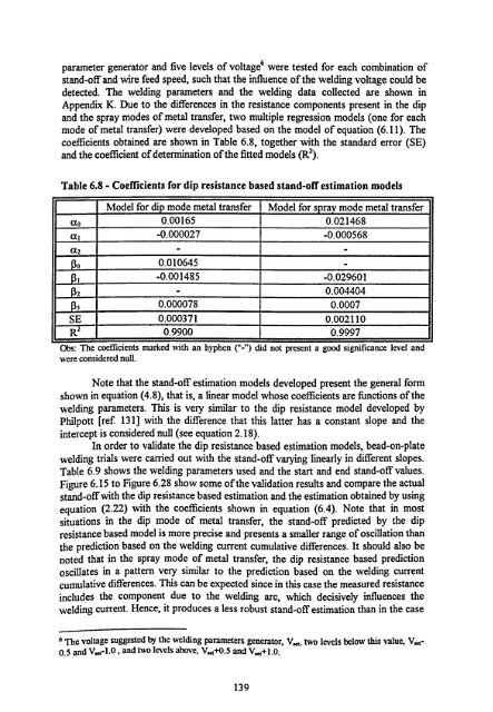
coefficients obtained are shown in Table 6.8, together with the standard error (SE)<br />
and the coefficient of determination of the fitted models (R2).<br />
Table 6.8 - Coefficients for dip resistance based stand-off estimation models<br />
Model for dip mode metal transfer Model for spray mode metal transfer<br />
0.00165 0.021468<br />
al -0.000027 -0.000568<br />
a2 - -<br />
0<br />
0.010645<br />
1 -0.001485 -0.029601<br />
2 - 0.004404<br />
3<br />
0.000078 0.0007<br />
SE 0.000371 0.002110<br />
R2 0.9900 0.9997<br />
Obs: The coefficients marked with an hyphen ("=) did not present a good significance level and<br />
were considered null.<br />
Note that the stand-off estimation models developed present the general form<br />
shown in equation (4.8), that is, a linear model whose coefficients are functions of the<br />
welding parameters. This is very similar to the dip resistance model developed by<br />
Philpott [ref. 131] with the difference that this latter has a constant slope and the<br />
intercept is considered null (see equation 2.18).<br />
In order to validate the dip resistance based estimation models, bead-on-plate<br />
welding trials were carried out with the stand-off varying linearly in different slopes.<br />
Table 6.9 shows the welding parameters used and the start and end stand-off values.<br />
Figure 6.15 to Figure 6.28 show some of the validation results and compare the actual<br />
stand-off with the dip resistance based estimation and the estimation obtained by using<br />
equation (2.22) with the coefficients shown in equation (6.4). Note that in most<br />
situations in the dip mode of metal transfer, the stand-off predicted by the dip<br />
resistance based model is more precise and presents a smaller range of oscillation than<br />
the prediction based on the welding current cumulative differences. It should also be<br />
noted that in the spray mode of metal transfer, the dip resistance based prediction<br />
oscillates in a pattern very similar to the prediction based on the welding current<br />
cumulative differences. This can be expected since in this case the measured resistance<br />
includes the component due to the welding arc, which decisively influences the<br />
welding current. Hence, it produces a less robust stand-off estimation than in the case<br />
6 The voltage suggested by the welding parameters generator, V,., two levels below this value, V. 4-<br />
0.5 and V e-1.0 , and two levels above, V, a+0.5 and V,, +1.0.<br />
139<br />
-


