

LIBRARY ı6ıul 0) - Cranfield University
LIBRARY ı6ıul 0) - Cranfield University
LIBRARY ı6ıul 0) - Cranfield University

You also want an ePaper? Increase the reach of your titles
YUMPU automatically turns print PDFs into web optimized ePapers that Google loves.
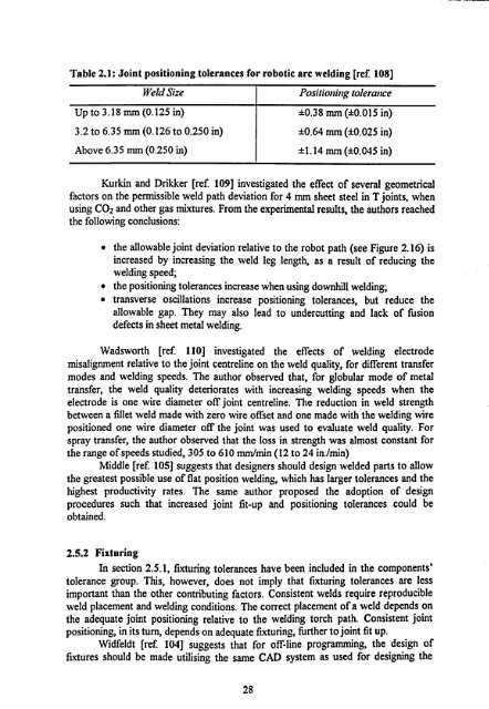
Table 2.1: Joint positioning tolerances for robotic arc welding [ref 108]<br />
Weld Size I Positioning tolerance<br />
Up to 3.18 mm (0.125 in) ±0.38 mm<br />
(±0.015 in)<br />
3.2 to 6.35 mm (0.126 to 0.250 in) ±0.64 nun (±0.025 in)<br />
Above 6.35 mm (0.250 in) ±1.14 mm (±0.045 in)<br />
Kurkin and Drikker [ref. 109] investigated the effect of several geometrical<br />
factors on the permissible weld path deviation for 4 mm sheet steel in T joints, when<br />
using CO2 and other gas mixtures. From the experimental results, the authors reached<br />
the following conclusions:<br />
" the allowable joint deviation relative to the robot path (see Figure 2.16) is<br />
increased by increasing the weld leg length, as a result of reducing the<br />
welding speed;<br />
" the positioning tolerances increase when using downhill welding;<br />
" transverse oscillations increase positioning tolerances, but reduce the<br />
allowable gap. They may also lead to undercutting and lack of fusion<br />
defects in sheet metal welding.<br />
Wadsworth [ref. 110] investigated the effects of welding electrode<br />
misalignment relative to the joint centreline on the weld quality, for different transfer<br />
modes and welding speeds. The author observed that, for globular mode of metal<br />
transfer, the weld quality deteriorates with increasing welding speeds when the<br />
electrode is one wire diameter off joint centreline. The reduction in weld strength<br />
between a fillet weld made with zero wire offset and one made with the welding wire<br />
positioned one wire diameter off the joint was used to evaluate weld quality. For<br />
spray transfer, the author observed that the loss in strength was almost constant for<br />
the range of speeds studied, 305 to 610 mm/min (12 to 24 in. /min)<br />
Middle [ref. 105] suggests that designers should design welded parts to allow<br />
the greatest possible use of flat position welding, which has larger tolerances and the<br />
highest productivity rates. The same author proposed the adoption of design<br />
procedures such that increased joint fit-up and positioning tolerances could be<br />
obtained.<br />
2.5.2 Fixturing<br />
In section 2.5.1, fixturing tolerances have been included in the components'<br />
tolerance group. This, however, does not imply that fixturing tolerances are less<br />
important than the other contributing factors. Consistent welds require reproducible<br />
weld placement and welding conditions. The correct placement of a weld depends on<br />
the adequate joint positioning relative to the welding torch path. Consistent joint<br />
positioning, in its turn, depends on adequate fixturing, further to joint fit up.<br />
Widfeldt [ref. 104] suggests that for off-line programming, the design of<br />
fixtures should be made utilising the same CAD system as used for designing the<br />
28


