

LIBRARY ı6ıul 0) - Cranfield University
LIBRARY ı6ıul 0) - Cranfield University
LIBRARY ı6ıul 0) - Cranfield University

You also want an ePaper? Increase the reach of your titles
YUMPU automatically turns print PDFs into web optimized ePapers that Google loves.
movements, in which the robot and the table should move to achieve the required<br />
relative position at the weld start point. The sequence of signals and their purpose<br />
were already described in section 4.1.3.1.<br />
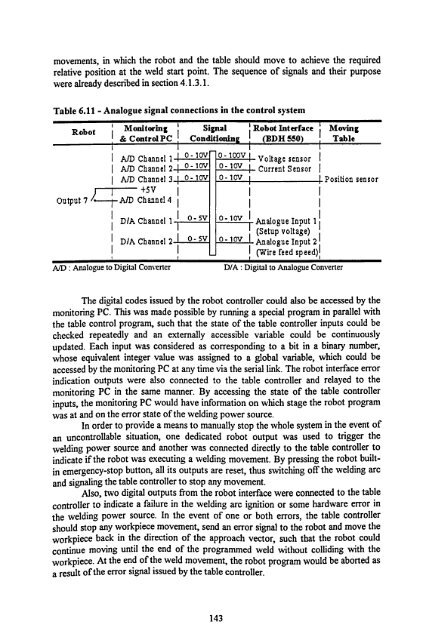
Table 6.11 - Analogue signal connections in the control system<br />
Robot<br />
Output 7 ---rAM<br />
Monitoring ' Signal ' Robot Interface Moving<br />
& Control PC Conditioning (BDH 550) Table<br />
0-iov<br />
A! D Channel 1 0-100V Voltage sensor<br />
A/D Channel 2 o- 1ov 0- 10H Current Sensor<br />
A/D Channel 3 0-10v o- lov Position sensor<br />
+SV<br />
Channel4<br />
t<br />
D/A Channel 1 0- 5v 0- lov Analogue Input 1<br />
(Setup voltage)<br />
D/A Channel 2 0- SV 0-10v Analogue Input 2<br />
1 (Wire feed speed))<br />
A/D : Analogue to Digital Converter D/A: Digital to Analogue Converter<br />
The digital codes issued by the robot controller could also be accessed by the<br />
monitoring PC. This was made possible by running a special program in parallel with<br />
the table control program, such that the state of the table controller inputs could be<br />
checked repeatedly and an externally accessible variable could be continuously<br />
updated. Each input was considered as corresponding to a bit in a binary number,<br />
whose equivalent integer value was assigned to a global variable, which could be<br />
accessed by the monitoring PC at any time via the serial link. The robot interface error<br />
indication outputs were also connected to the table controller and relayed to the<br />
monitoring PC in the same manner. By accessing the state of the table controller<br />
inputs, the monitoring PC would have information on which stage the robot program<br />
was at and on the error state of the welding power source.<br />
In order to provide a means to manually stop the whole system in the event of<br />
an uncontrollable situation, one dedicated robot output was used to trigger the<br />
welding power source and another was connected directly to the table controller to<br />
indicate if the robot was executing a welding movement. By pressing the robot built-<br />
in emergency-stop button, all its outputs are reset, thus switching off the welding arc<br />
and signaling the table controller to stop any movement.<br />
Also, two digital outputs from the robot interface were connected to the table<br />
controller to indicate a failure in the welding arc ignition or some hardware error in<br />
the welding power source. In the event of one or both errors, the table controller<br />
should stop any workpiece movement, send an error signal to the robot and move the<br />
workpiece back in the direction of the approach vector, such that the robot could<br />
continue moving until the end of the programmed weld without colliding with the<br />
workpiece. At the end of the weld movement, the robot program would be aborted as<br />
a result of the error signal issued by the table controller.<br />
143


