- Page 1 and 2:
EnterpriseServer ES7000Model7600RG2
- Page 3 and 4:
Contents Section 1. Safety Section
- Page 5 and 6:
Section 5. Parts listing Replaceabl
- Page 7 and 8:
Appendix A. Services and Support Ap
- Page 9 and 10:
Tables 3-1. Power-supply LEDs . . .
- Page 11 and 12:
Section 1 Safety Before installing
- Page 13 and 14:
3. Check the power cord: • Make s
- Page 15 and 16:
DANGER Statement 2: Electrical curr
- Page 17 and 18:
CAUTION: Statement 5: Use safe prac
- Page 19 and 20:
Section 2 Start here You can solve
- Page 21 and 22:
Many configuration problems are cau
- Page 23 and 24:
Section 3 Introduction This Problem
- Page 25 and 26:
Notes: • Racks are marked in vert
- Page 27 and 28:
• Serial-attached SCSI (SAS) cont
- Page 29 and 30:
Electrostatic-discharge connector:
- Page 31 and 32:
Notes: Rear view • For optimum fa
- Page 33 and 34:
AC power LED: Each hot-swap power s
- Page 35 and 36:
Power-supply LEDs AC DC Error On Of
- Page 37 and 38:
The server can be turned off in any
- Page 39 and 40:
Memory-card connectors on the micro
- Page 41 and 42:
The following table describes the f
- Page 43 and 44:
The following table describes the f
- Page 45 and 46:
Introduction 3850 7281-000 3-23
- Page 47 and 48:
Section 4 Diagnostics This chapter
- Page 49 and 50:
• DSA log: This log is generated
- Page 51 and 52:
Error code Description Action 00100
- Page 53 and 54:
Error code Description Action 00510
- Page 55 and 56:
Error code Description Action 20180
- Page 57 and 58:
Error code Description Action 30580
- Page 59 and 60:
Error code Description Action 38180
- Page 61 and 62:
Troubleshooting tables Use the trou
- Page 63 and 64:
• If an action step is preceded b
- Page 65 and 66:
USB keyboard, mouse, or pointing-de
- Page 67 and 68:
Symptom Action The amount of system
- Page 69 and 70:
• Follow the suggested actions in
- Page 71 and 72:
Symptom Action The monitor has scre
- Page 73 and 74:
performed only by a trained service
- Page 75 and 76:
Serial-device problems • Follow t
- Page 77 and 78:
Video problems See Monitor or video
- Page 79 and 80:
Notes: • You must remove the memo
- Page 81 and 82:
Remind button The following illustr
- Page 83 and 84:
Lit light path diagnostics LED with
- Page 85 and 86:
Lit light path diagnostics LED with
- Page 87 and 88:
Lit light path diagnostics LED with
- Page 89 and 90:
The following illustration shows th
- Page 91 and 92:
• System configuration • Vital
- Page 93 and 94:
000 The server passed the test. Do
- Page 95 and 96:
Table 4-2. DSA messages (cont.) Mes
- Page 97 and 98:
Table 4-2. DSA messages (cont.) Mes
- Page 99 and 100:
Table 4-2. DSA messages (cont.) Mes
- Page 101 and 102:
Table 4-2. DSA messages (cont.) Mes
- Page 103 and 104:
Table 4-2. DSA messages (cont.) Mes
- Page 105 and 106:
Table 4-2. DSA messages (cont.) Mes
- Page 107 and 108:
Table 4-2. DSA messages (cont.) Mes
- Page 109 and 110:
Table 4-2. DSA messages (cont.) Mes
- Page 111 and 112:
Table 4-2. DSA messages (cont.) Mes
- Page 113 and 114:
Table 4-2. DSA messages (cont.) Mes
- Page 115 and 116:
Table 4-2. DSA messages (cont.) Mes
- Page 117 and 118:
Table 4-2. DSA messages (cont.) Mes
- Page 119 and 120:
Table 4-2. DSA messages (cont.) Mes
- Page 121 and 122:
Table 4-2. DSA messages (cont.) Mes
- Page 123 and 124:
Table 4-2. DSA messages (cont.) Mes
- Page 125 and 126:
Table 4-2. DSA messages (cont.) Mes
- Page 127 and 128:
Table 4-2. DSA messages (cont.) Mes
- Page 129 and 130:
Table 4-2. DSA messages (cont.) Mes
- Page 131 and 132:
Table 4-2. DSA messages (cont.) Mes
- Page 133 and 134:
Table 4-2. DSA messages (cont.) Mes
- Page 135 and 136:
Table 4-2. DSA messages (cont.) Mes
- Page 137 and 138:
Table 4-2. DSA messages (cont.) Mes
- Page 139 and 140:
Table 4-2. DSA messages (cont.) Mes
- Page 141 and 142:
Table 4-2. DSA messages (cont.) Mes
- Page 143 and 144:
Table 4-2. DSA messages (cont.) Mes
- Page 145 and 146:
Table 4-2. DSA messages (cont.) Mes
- Page 147 and 148:
Table 4-2. DSA messages (cont.) Mes
- Page 149 and 150:
Table 4-2. DSA messages (cont.) Mes
- Page 151 and 152:
Table 4-2. DSA messages (cont.) Mes
- Page 153 and 154:
Table 4-2. DSA messages (cont.) Mes
- Page 155 and 156:
Table 4-2. DSA messages (cont.) Mes
- Page 157 and 158:
Table 4-2. DSA messages (cont.) Mes
- Page 159 and 160:
Table 4-2. DSA messages (cont.) Mes
- Page 161 and 162:
Table 4-2. DSA messages (cont.) Mes
- Page 163 and 164:
Table 4-2. DSA messages (cont.) Mes
- Page 165 and 166:
Table 4-2. DSA messages (cont.) Mes
- Page 167 and 168:
Table 4-2. DSA messages (cont.) Mes
- Page 169 and 170:
Table 4-2. DSA messages (cont.) Mes
- Page 171 and 172:
Table 4-2. DSA messages (cont.) Mes
- Page 173 and 174:
Table 4-2. DSA messages (cont.) Mes
- Page 175 and 176:
Table 4-2. DSA messages (cont.) Mes
- Page 177 and 178:
Error Error messages might require
- Page 179 and 180:
Table 4-3. Integrated management mo
- Page 181 and 182:
Table 4-3. Integrated management mo
- Page 183 and 184:
Table 4-3. Integrated management mo
- Page 185 and 186:
Table 4-3. Integrated management mo
- Page 187 and 188: Table 4-3. Integrated management mo
- Page 189 and 190: Table 4-3. Integrated management mo
- Page 191 and 192: Table 4-3. Integrated management mo
- Page 193 and 194: Table 4-3. Integrated management mo
- Page 195 and 196: Table 4-3. Integrated management mo
- Page 197 and 198: Table 4-3. Integrated management mo
- Page 199 and 200: Table 4-3. Integrated management mo
- Page 201 and 202: Table 4-3. Integrated management mo
- Page 203 and 204: Table 4-3. Integrated management mo
- Page 205 and 206: Table 4-3. Integrated management mo
- Page 207 and 208: Table 4-3. Integrated management mo
- Page 209 and 210: Table 4-3. Integrated management mo
- Page 211 and 212: Table 4-3. Integrated management mo
- Page 213 and 214: Damaged data in CMOS memory or dama
- Page 215 and 216: Section 5 Parts listing The followi
- Page 217 and 218: Replaceable server components Repla
- Page 219 and 220: Index Description Table 5-1. Parts
- Page 221 and 222: For units intended to be operated a
- Page 223 and 224: Section 6 Removing and replacing se
- Page 225 and 226: System reliability guidelines To he
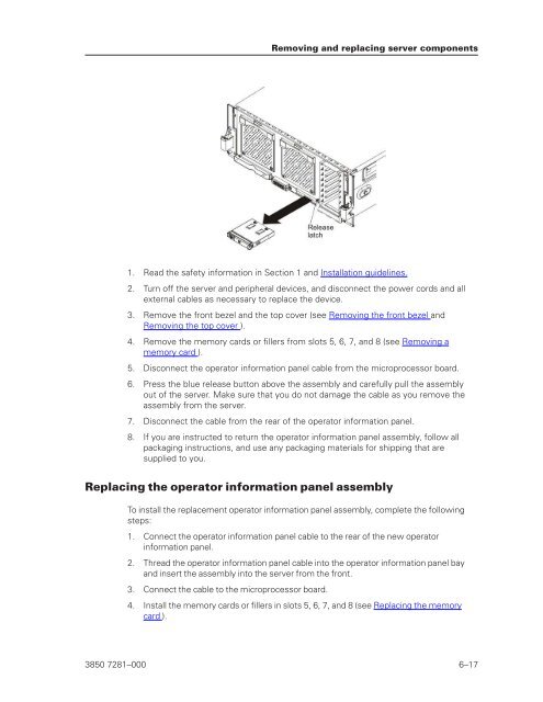
- Page 227 and 228: Removing and replacing server compo
- Page 229 and 230: You can install one or more optiona
- Page 231 and 232: 4. Slide the top cover forward and
- Page 233 and 234: Removing an adapter Removing and re
- Page 235 and 236: 6. Remove the battery: a. Use one f
- Page 237: 6. Start the Setup utility and rese
- Page 241 and 242: 3. Open the fan-release handle by p
- Page 243 and 244: Removing a hot-swap hard disk drive
- Page 245 and 246: Caution Never remove the cover on a
- Page 247 and 248: Removing a QPI wrap card To remove
- Page 249 and 250: Memory cards and memory modules (DI
- Page 251 and 252: • The following illustration show
- Page 253 and 254: Table 6-3. High-performance memory-
- Page 255 and 256: Memory card/DIMM error LED: When th
- Page 257 and 258: Replacing the memory card To instal
- Page 259 and 260: Removing and replacing FRUs FRUs mu
- Page 261 and 262: 6. Remove the memory cards and memo
- Page 263 and 264: Replacing the I/O-board shuttle To
- Page 265 and 266: 13. Remove the cables from the serv
- Page 267 and 268: Removing and replacing server compo
- Page 269 and 270: 4. Slide the RAID adapter carrier a
- Page 271 and 272: 4. Connect the cables and power cor
- Page 273 and 274: 4. Slide the hard disk drive backpl
- Page 275 and 276: To remove a microprocessor and heat
- Page 277 and 278: 9. Place the microprocessor install
- Page 279 and 280: 3. Install the replacement micropro
- Page 281 and 282: c. Position the heat sink above the
- Page 283 and 284: 1. Read the safety information in S
- Page 285 and 286: 17. Using the Advanced Settings Uti
- Page 287 and 288: Section 7 Configuration information
- Page 289 and 290:
For information about using this pr
- Page 291 and 292:
o Commands on USB Interface Prefere
- Page 293 and 294:
Passwords - Clear Administrator Pas
- Page 295 and 296:
1. Turn off the server. 2. Restart
- Page 297 and 298:
3. Select System Settings → Integ
- Page 299 and 300:
Advanced Settings Utility program C
- Page 301 and 302:
Appendix A Services and Support Thi
- Page 303 and 304:
Service Task Responsibility Billabl
- Page 305 and 306:
Appendix B Notices Important notes
- Page 307 and 308:
For the European Union: Notice: Thi
- Page 309 and 310:
European Union EMC Directive confor
- Page 311 and 312:
Russia Electromagnetic Interference
- Page 313 and 314:
Index A ABR, automatic boot failure
- Page 315 and 316:
optional devices, 4-26 pointing dev
- Page 317 and 318:
power-on, 3-11 rear, 3-11 front, 3-
- Page 319 and 320:
hard disk drive, 6-21 heat sink, 6-
- Page 322:
© Portions copyright Unisys Corpor