

User's Manual AXF Magnetic Flowmeter Integral ... - Yokogawa
User's Manual AXF Magnetic Flowmeter Integral ... - Yokogawa
User's Manual AXF Magnetic Flowmeter Integral ... - Yokogawa

You also want an ePaper? Increase the reach of your titles
YUMPU automatically turns print PDFs into web optimized ePapers that Google loves.
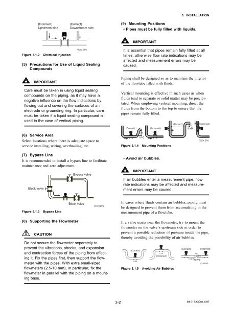
(Incorrect)<br />
Upstream side<br />
(Correct)<br />
Downstream side<br />
3. INSTALLATION<br />
(9) Mounting Positions<br />
• Pipes must be fully filled with liquids.<br />
IMPORTANT<br />
Figure 3.1.2<br />
Chemical Injection<br />
F0302.EPS<br />
(5) Precautions for Use of Liquid Sealing<br />
Compounds<br />
It is essential that pipes remain fully filled at all<br />
times, otherwise flow rate indications may be<br />
affected and measurement errors may be<br />
caused.<br />
IMPORTANT<br />
Care must be taken in using liquid sealing<br />
compounds on the piping, as it may have a<br />
negative influence on the flow indications by<br />
flowing out and covering the surfaces of an<br />
electrode or grounding ring. In particular, care<br />
must be taken if a liquid sealing compound is<br />
used in the case of vertical piping.<br />
(6) Service Area<br />
Select locations where there is adequate space to<br />
service installing, wiring, overhauling, etc.<br />
(7) Bypass Line<br />
It is recommended to install a bypass line to facilitate<br />
maintenance and zero adjustment.<br />
Block valve<br />
Bypass valve<br />
Piping shall be designed so as to maintain the interior<br />
of the flowtube filled with fluids.<br />
Vertical mounting is effective in such cases as when<br />
fluids tend to separate or solid matter may be precipitated.<br />
When employing vertical mounting, direct the<br />
fluids from the bottom to the top to ensure that the<br />
pipes remain fully filled.<br />
(Correct)<br />
Figure 3.1.4<br />
h<br />
h>0<br />
(Incorrect)<br />
Mounting Positions<br />
• Avoid air bubbles.<br />
IMPORTANT<br />
(Correct)<br />
h<br />
h>0<br />
(Incorrect)<br />
F0304.EPS<br />
If air bubbles enter a measurement pipe, flow<br />
rate indications may be affected and measurement<br />
errors may be caused.<br />
Figure 3.1.3<br />
Bypass Line<br />
Block valve<br />
F0303.EPS<br />
In cases where fluids contain air bubbles, piping must<br />
be designed to prevent them from accumulating in the<br />
measurement pipe of a flowtube.<br />
(8) Supporting the <strong>Flowmeter</strong><br />
CAUTION<br />
Do not secure the flowmeter separately to<br />
prevent the vibrations, shocks, and expansion<br />
and contraction forces of the piping from affecting<br />
it. Fix the pipes first, then support the flowmeter<br />
with the pipes. With extra small-sized<br />
flowmeters (2.5-10 mm), in particular, fix the<br />
flowmeter in parallel with the piping on a mounting<br />
base.<br />
If a valve exists near the flowmeter, try to mount the<br />
flowmeter on the valve’s upstream side in order to<br />
prevent a possible reduction of pressure inside the pipe,<br />
thereby avoiding the possibility of air bubbles.<br />
(Correct)<br />
Figure 3.1.5<br />
(Incorrect)<br />
Avoiding Air Bubbles<br />
(Correct)<br />
Valve<br />
(Incorrect)<br />
F10.EPS<br />
3-2<br />
IM 01E20D01-01E


