

User's Manual AXF Magnetic Flowmeter Integral ... - Yokogawa
User's Manual AXF Magnetic Flowmeter Integral ... - Yokogawa
User's Manual AXF Magnetic Flowmeter Integral ... - Yokogawa

You also want an ePaper? Increase the reach of your titles
YUMPU automatically turns print PDFs into web optimized ePapers that Google loves.
4. WIRING<br />
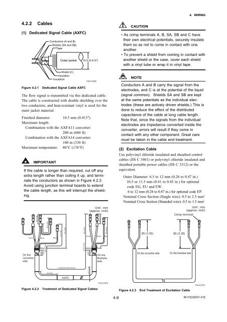
4.2.2 Cables<br />
(1) Dedicated Signal Cable (<strong>AXF</strong>C)<br />
Figure 4.2.1<br />
Conductors (A and B)<br />
Shields (SA and SB)<br />
Tape<br />
Outer jacket 10.5 (0.413")<br />
Shield (C)<br />
Insulation<br />
Insulation<br />
Dedicated Signal Cable <strong>AXF</strong>C<br />
F0417.EPS<br />
The flow signal is transmitted via this dedicated cable.<br />
The cable is constructed with double shielding over the<br />
two conductors, and heat-resistant vinyl is used for the<br />
outer jacket material.<br />
Finished diameter: 10.5 mm (0.413")<br />
Maximum length:<br />
Combination with the <strong>AXF</strong>A11 converter:<br />
200 m (660 ft)<br />
Combination with the <strong>AXF</strong>A14 converter:<br />
100 m (330 ft)<br />
Maximum temperature: 80°C (176°F)<br />
SA<br />
IMPORTANT<br />
If the cable is longer than required, cut off any<br />
extra length rather than coiling it up, and terminate<br />
the conductors as shown in Figure 4.2.2.<br />
Avoid using junction terminal boards to extend<br />
the cable length, as this will interrupt the shielding.<br />
A<br />
On the<br />
converter<br />
side<br />
25 (0.98)<br />
B<br />
50 (1.97)<br />
SB<br />
150 5<br />
(5.9)<br />
8(0.3) max.<br />
C<br />
70 (2.76)<br />
60 (2.36)<br />
White Black Red<br />
90 (3.54)<br />
Unit : mm<br />
(approx. inch)<br />
A<br />
150 5 8 (0.3) max.<br />
(5.9)<br />
B<br />
55 (2.17)<br />
C<br />
90 (3.54)<br />
White Black Red<br />
On the<br />
flowtube<br />
side<br />
CAUTION<br />
• As crimp terminals A, B, SA, SB and C have<br />
their own electrical potentials, securely insulate<br />
them so as not to come in contact with one<br />
another.<br />
• To prevent a shield from coming in contact with<br />
another shield or the case, cover each shield<br />
with a vinyl tube or wrap it in vinyl tape.<br />
NOTE<br />
Conductors A and B carry the signal from the<br />
electrodes, and C is at the potential of the liquid<br />
(signal common). Shields SA and SB are kept<br />
at the same potentials as the individual electrodes<br />
(these are actively driven shields.) This is<br />
done to reduce the effect of the distributed<br />
capacitance of the cable at long cable length.<br />
Note that, since the signals from the individual<br />
electrodes are impedance converted inside the<br />
converter, errors will result if they come in<br />
contact with any other component. Great care<br />
must be taken in the cable end treatment.<br />
(2) Excitation Cable<br />
Use polyvinyl chloride insulated and sheathed control<br />
cables (JIS C 3401) or polyvinyl chloride insulated and<br />
sheathed portable power cables (JIS C 3312) or the<br />
equivalent.<br />
Outer Diameter: 6.5 to 12 mm (0.26 to 0.47 in.)<br />
10.5 or 11.5 mm (0.41 to 0.45 in.) for optional<br />
code EG, EU and EW.<br />
6 to 12 mm (0.24 to 0.47 in.) for optional code EP.<br />
Nominal Cross Section (Single wire): 0.5 to 2.5 mm 2<br />
Nominal Cross Section (Stranded wire): 0.5 to 1.5 mm 2<br />
EX1<br />
EX2<br />
85 (3.35)<br />
On the converter side<br />
Unit : mm<br />
(approx. inch)<br />
Crimp terminal<br />
85 (3.35)<br />
EX1<br />
On the flowtube side<br />
EX2<br />
20 (0.8)<br />
L (Specified Dimensions)<br />
<strong>AXF</strong>C<br />
10.5 (0.4)<br />
Figure 4.2.2<br />
Treatment of Dedicated Signal Cables<br />
F0418.EPS<br />
Figure 4.2.3<br />
End Treatment of Excitation Cable<br />
F0419.EPS<br />
4-9<br />
IM 01E20D01-01E


