

User's Manual AXF Magnetic Flowmeter Integral ... - Yokogawa
User's Manual AXF Magnetic Flowmeter Integral ... - Yokogawa
User's Manual AXF Magnetic Flowmeter Integral ... - Yokogawa

Create successful ePaper yourself
Turn your PDF publications into a flip-book with our unique Google optimized e-Paper software.
3. INSTALLATION<br />
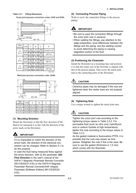
Table 3.3.1 Fitting Dimensions<br />
Screw joint (process connection codes: GUR and GUN)<br />
D<br />
(2) Connecting Process Piping<br />
Weld or screw the connection fittings to the process<br />
piping.<br />
A<br />
B C<br />
0<br />
-0.1<br />
IMPORTANT<br />
4<br />
(0.16)<br />
Size<br />
mm(inch) Code A B C D<br />
2.5<br />
(0.1)<br />
5<br />
(0.2)<br />
10<br />
(0.4)<br />
11.5(0.45)<br />
GUR<br />
GUN<br />
GUR<br />
GUN<br />
GUR<br />
GUN<br />
22<br />
(0.87)<br />
22<br />
(0.87)<br />
22<br />
(0.87)<br />
22<br />
(0.87)<br />
25<br />
(0.98)<br />
25<br />
(0.98)<br />
30(1.18)<br />
8<br />
(0.31)<br />
8<br />
(0.31)<br />
8<br />
(0.31)<br />
8<br />
(0.31)<br />
10<br />
(0.39)<br />
10<br />
(0.39)<br />
18.5<br />
(0.73)<br />
18.5<br />
(0.73)<br />
18.5<br />
(0.73)<br />
18.5<br />
(0.73)<br />
22.5<br />
(0.89)<br />
22.5<br />
(0.89)<br />
R1/4(PT1/4)<br />
NPT1/4<br />
R1/4(PT1/4)<br />
NPT1/4<br />
R3/8(PT3/8)<br />
NPT3/8<br />
T0301.EPS<br />
Weld joint (process connection code: GUW)<br />
•Be sure to pass the connection fittings through<br />
the union joint nuts in advance.<br />
•When welding the fittings, pay attention to the<br />
edge preparation, level differences between the<br />
fittings and the piping, and the welding current<br />
to avoid deforming the piping or causing<br />
stagnation portion of the fluid.<br />
(3) Positioning the <strong>Flowmeter</strong><br />
Install the flowmeter on a mounting base and position<br />
it so that the center axis of the flowtube is aligned with<br />
that of the process piping. Then screw the union joint<br />
nuts to the connecting ports of the flowmeter.<br />
CAUTION<br />
A B<br />
4<br />
(0.16) 35(1.38)<br />
10(0.39)<br />
C<br />
+0.3<br />
0<br />
D<br />
0<br />
-0.1<br />
Ceramics pipes may be damaged if the nuts are<br />
tightened when the center axes are not properly<br />
aligned.<br />
Size<br />
mm(inch)<br />
Code<br />
2.5 (0.1) GUW<br />
5 (0.2) GUW<br />
10 (0.4) GUW<br />
A B C D<br />
22(0.87) 8(0.31) 14.3(0.56) 18.5(0.73)<br />
22(0.87) 8(0.31) 14.3(0.56) 18.5(0.73)<br />
25(0.98) 10(0.39) 17.8(0.70) 22.5(0.89)<br />
T0302.EPS<br />
(1) Mounting Direction<br />
Mount the flowmeter so that the flow direction of the<br />
fluid to be measured is in line with the direction of the<br />
arrow mark on the flowmeter.<br />
IMPORTANT<br />
If it is impossible to match the direction of the<br />
arrow mark, the direction of the electrical connection<br />
can be changed. Refer to Section 5.1 to<br />
do this properly.<br />
In case the fluid being measured flows against<br />
the arrow direction, refer to the parameter J20:<br />
Flow Direction in the user’s manual of the<br />
<strong>AXF</strong>A11 <strong>Magnetic</strong> <strong>Flowmeter</strong> Remote Converter<br />
(IM 01E20C01-01E) or the <strong>AXF</strong>A14 <strong>Magnetic</strong><br />
<strong>Flowmeter</strong> Remote Converter/<strong>AXF</strong> <strong>Integral</strong><br />
<strong>Flowmeter</strong> [Software Edition] (IM 01E20C02-<br />
01E).<br />
(4) Tightening Nuts<br />
Use a torque wrench to tighten the union joint nuts.<br />
CAUTION<br />
Tighten the union joint nuts according to the<br />
tightening torque values in Table 3.3.2. For<br />
permeable fluid (such as nitric acid, hydrofluoric<br />
acid or sodium hydrate at high temperature),<br />
tighten the nuts according to the torque values in<br />
Table 3.3.3.<br />
As the gasket material is fluorocarbon PTFE, it is<br />
possible that the nuts may loosen as time<br />
passes. Retighten the nuts if this is the case. Be<br />
sure to use the gasket (thickness is 1.5 mm)<br />
which comes with the flowmeter.<br />
3-5<br />
IM 01E20D01-01E


