

User's Manual AXF Magnetic Flowmeter Integral ... - Yokogawa
User's Manual AXF Magnetic Flowmeter Integral ... - Yokogawa
User's Manual AXF Magnetic Flowmeter Integral ... - Yokogawa

Create successful ePaper yourself
Turn your PDF publications into a flip-book with our unique Google optimized e-Paper software.
4. WIRING<br />
4.2.4 Wiring Connections<br />
PF1/2<br />
Gasket<br />
WARNING<br />
Before wiring, be sure that the power supply for<br />
<strong>AXF</strong>A11 or <strong>AXF</strong>A14 converter has been turned<br />
off to prevent an electrical shock.<br />
Figure 4.2.5<br />
Cable<br />
Tightening gland<br />
Washer<br />
When working on conduit pipes or flexible pipes (PF1/2 only)<br />
Waterproof Gland with Union Joint<br />
(Optional code EU)<br />
F0421.EPS<br />
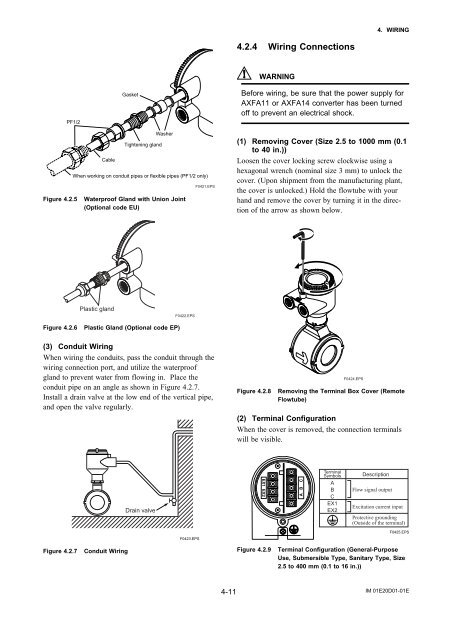
(1) Removing Cover (Size 2.5 to 1000 mm (0.1<br />
to 40 in.))<br />
Loosen the cover locking screw clockwise using a<br />
hexagonal wrench (nominal size 3 mm) to unlock the<br />
cover. (Upon shipment from the manufacturing plant,<br />
the cover is unlocked.) Hold the flowtube with your<br />
hand and remove the cover by turning it in the direction<br />
of the arrow as shown below.<br />
Plastic gland<br />
F0422.EPS<br />
Figure 4.2.6<br />
Plastic Gland (Optional code EP)<br />
(3) Conduit Wiring<br />
When wiring the conduits, pass the conduit through the<br />
wiring connection port, and utilize the waterproof<br />
gland to prevent water from flowing in. Place the<br />
conduit pipe on an angle as shown in Figure 4.2.7.<br />
Install a drain valve at the low end of the vertical pipe,<br />
and open the valve regularly.<br />
Figure 4.2.8<br />
F0424.EPS<br />
Removing the Terminal Box Cover (Remote<br />
Flowtube)<br />
(2) Terminal Configuration<br />
When the cover is removed, the connection terminals<br />
will be visible.<br />
Drain valve<br />
Terminal<br />
Symbols<br />
A<br />
B<br />
C<br />
EX1<br />
EX2<br />
Description<br />
Flow signal output<br />
Excitation current input<br />
Protective grounding<br />
(Outside of the terminal)<br />
F0423.EPS<br />
F0425.EPS<br />
Figure 4.2.7<br />
Conduit Wiring<br />
Figure 4.2.9<br />
Terminal Configuration (General-Purpose<br />
Use, Submersible Type, Sanitary Type, Size<br />
2.5 to 400 mm (0.1 to 16 in.))<br />
4-11<br />
IM 01E20D01-01E


