

User's Manual AXF Magnetic Flowmeter Integral ... - Yokogawa
User's Manual AXF Magnetic Flowmeter Integral ... - Yokogawa
User's Manual AXF Magnetic Flowmeter Integral ... - Yokogawa

Create successful ePaper yourself
Turn your PDF publications into a flip-book with our unique Google optimized e-Paper software.
3. INSTALLATION<br />
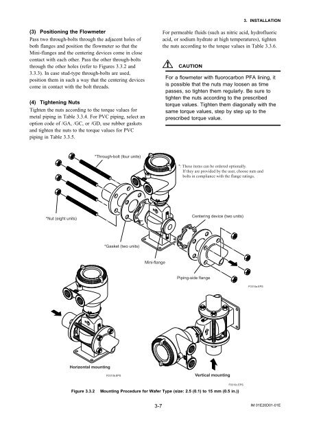
(3) Positioning the <strong>Flowmeter</strong><br />
Pass two through-bolts through the adjacent holes of<br />
both flanges and position the flowmeter so that the<br />
Mini-flanges and the centering devices come in close<br />
contact with each other. Pass the other through-bolts<br />
through the other holes (refer to Figures 3.3.2 and<br />
3.3.3). In case stud-type through-bolts are used,<br />
position them in such a way that the centering devices<br />
come in contact with the bolt threads.<br />
(4) Tightening Nuts<br />
Tighten the nuts according to the torque values for<br />
metal piping in Table 3.3.4. For PVC piping, select an<br />
option code of /GA, /GC, or /GD, use rubber gaskets<br />
and tighten the nuts to the torque values for PVC<br />
piping in Table 3.3.5.<br />
For permeable fluids (such as nitric acid, hydrofluoric<br />
acid, or sodium hydrate at high temperatures), tighten<br />
the nuts according to the torque values in Table 3.3.6.<br />
CAUTION<br />
For a flowmeter with fluorocarbon PFA lining, it<br />
is possible that the nuts may loosen as time<br />
passes, so tighten them regularly. Be sure to<br />
tighten the nuts according to the prescribed<br />
torque values. Tighten them diagonally with the<br />
same torque values, step by step up to the<br />
prescribed torque value.<br />
*Through-bolt (four units)<br />
*: These items can be ordered optionally.<br />
If they are provided by the user, choose nuts and<br />
bolts in compliance with the flange ratings.<br />
*Nut (eight units)<br />
Centering device (two units)<br />
*Gasket (two units)<br />
Mini-flange<br />
Piping-side flange<br />
F0310a.EPS<br />
Horizontal mounting<br />
F0310b.EPS<br />
Vertical mounting<br />
Figure 3.3.2<br />
F0310c.EPS<br />
Mounting Procedure for Wafer Type (size: 2.5 (0.1) to 15 mm (0.5 in.))<br />
3-7<br />
IM 01E20D01-01E


