

User's Manual AXF Magnetic Flowmeter Integral ... - Yokogawa
User's Manual AXF Magnetic Flowmeter Integral ... - Yokogawa
User's Manual AXF Magnetic Flowmeter Integral ... - Yokogawa

You also want an ePaper? Increase the reach of your titles
YUMPU automatically turns print PDFs into web optimized ePapers that Google loves.
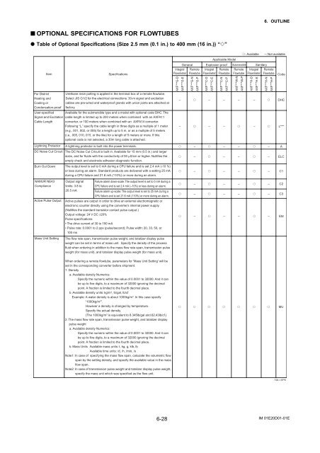
6. OUTLINE<br />
■ OPTIONAL SPECIFICATIONS FOR FLOWTUBES<br />
Table of Optional Specifications (Size 2.5 mm (0.1 in.) to 400 mm (16 in.)) “”<br />
: Available –: Not available<br />
Applicable Model<br />
Item<br />
For District<br />
Heating and<br />
Cooling or<br />
Condensation-proof<br />
User-specified<br />
Signal and Excitation<br />
Cable Length<br />
Specifications<br />
Urethane resin potting is applied in the terminal box of a remote flowtube.<br />
Select JIS G1/2 for the electrical connections. 30-m signal and excitation<br />
cables are pre-wired and waterproof grands with union joints are attached at<br />
factory.<br />
Available for the submersible type and a model with optional code DHC. The<br />
cable length is limited up to 200 meters when combined with an <strong>AXF</strong>A11<br />
converter, or 100 meters when combined with an <strong>AXF</strong>A14 converter.<br />
Following “L,” specify the cable length in three digits as a multiple of 1 meter<br />
(e.g., 001, 002, or 005) for a length up to 5 m, or as a multiple of 5 meters<br />
(i.e., 005, 010, 015, or the like) for a length of 5 meters or more. If this<br />
optional code is not selected, a 30m long cable is attached.<br />
<strong>Integral</strong><br />
<strong>Flowmeter</strong><br />
<strong>AXF</strong>***G-D<br />
<strong>AXF</strong>***G-E<br />
General<br />
Remote<br />
Flowtube<br />
<strong>AXF</strong>***G-N<br />
<strong>AXF</strong>***G-P<br />
Explosion proof<br />
<strong>Integral</strong><br />
<strong>Flowmeter</strong><br />
<strong>AXF</strong>***C-D<br />
<strong>AXF</strong>***C-E<br />
Remote<br />
Flowtube<br />
<strong>AXF</strong>***C-N<br />
<strong>AXF</strong>***C-P<br />
Submersible<br />
Remote<br />
Flowtube<br />
<strong>AXF</strong>***W-N<br />
<strong>AXF</strong>***W-P<br />
<strong>AXF</strong>***H-D<br />
<strong>AXF</strong>***H-E<br />
Sanitary<br />
<strong>Integral</strong><br />
<strong>Flowmeter</strong><br />
Remote<br />
Flowtube<br />
<strong>AXF</strong>***H-N<br />
<strong>AXF</strong>***H-P<br />
Code<br />
– – – – – DHC<br />
– – – – L***<br />
Lightning Protector A lightning protector is built into the power terminals.<br />
DC Noise Cut Circuit The DC Noise Cut Circuit is built in. Available for 15 mm (0.5 in.) and larger<br />
sizes, and for fluids with the conductivity of 50 µS/cm or higher. Nullifies the<br />
empty check and electrode adhesion diagnostic function.<br />
Burn Out Down<br />
The output level is set to 0 mA during a CPU failure and is set 2.4 mA (-10 %)<br />
or less during an alarm. Standard products are delivered with a setting 25 mA<br />
during a CPU failure and 21.6 mA (110%) or more during an alarm.<br />
– – – – A<br />
– – – – ELC<br />
– – – – C1<br />
NAMUR NE43<br />
Compliance<br />
Active Pulse Output<br />
Mass Unit Setting<br />
Output signal<br />
limits: 3.8 to<br />
20.5 mA<br />
Failure alarm down-scale: The output level is set to 0 mA during a<br />
CPU failure and is set 2.4 mA (–10%) or less during an alarm.<br />
Failure alarm up-scale: The output level is set to 25 mA during a<br />
CPU failure and is set 21.6 mA (110%) or more during an alarm.<br />
Active pulses are output in order to drive an external electromagnetic or<br />
electronic counter directly using the converter’s internal power supply.<br />
(Nullifies the standard transistor contact pulse output.)<br />
Output voltage: 24 V DC ±20%<br />
Pulse specifications:<br />
• The drive current of 30 to 150 mA<br />
• Pulse rate: 0.0001 to 2 pps (pulse/second); Pulse width: 20, 33, 50, or<br />
100 ms<br />
The flow rate span, transmission pulse weight, and totalizer display pulse<br />
weight can be set in terms of mass unit. Specify the density of the process<br />
fluid when ordering in addition to the mass flow rate span, transmission pulse<br />
weight (for mass unit), and totalizer display pulse weight (for mass unit).<br />
– – – – C2<br />
– – – – C3<br />
– – – – EM<br />
When ordering a remote flowtube, parameters for 'Mass Unit Setting' will be<br />
set in the corresponding converter before shipment.<br />
1. Density<br />
a. Available density Numerics:<br />
Specify the numeric within the value of 0.0001 to 32000. And it can<br />
be up to five digits, to a maximum of 32000 ignoring the decimal<br />
point. A fraction is limited to the fourth decimal place.<br />
b. Available density units: kg/m 3 , lb/gal, lb/cf<br />
Example: A water density is about 1000kg/m 3 . In this case specify<br />
“1000kg/m 3 ”.<br />
However a density is changed by temperature.<br />
Specify the actual density.<br />
(The 1000kg/m 3 is equivalent to 8.345lb/gal and 62.43lb/cf.)<br />
2. The mass flow rate span, transmission pulse weight, and totalizer display<br />
pulse weight<br />
a. Available density Numerics:<br />
Specify the numeric within the value of 0.0001 to 32000. And it can<br />
be up to five digits, to a maximum of 32000 ignoring the decimal<br />
point. A fraction is limited to the fourth decimal place.<br />
b. Mass Units Available mass units: t, kg, g, klb, lb<br />
Available time units: /d, /h, /min, /s<br />
Note1: In case of specifying the mass flow span, calculate the volumetric flow<br />
span by the setting density, and specify the available value in the mass<br />
flow span.<br />
Note2: In case of transmission pulse weight and totalizer display pulse weight,<br />
specify the mass unit which was specified as the flow unit.<br />
MU<br />
T26-1.EPS<br />
6-28<br />
IM 01E20D01-01E


