

User's Manual AXF Magnetic Flowmeter Integral ... - Yokogawa
User's Manual AXF Magnetic Flowmeter Integral ... - Yokogawa
User's Manual AXF Magnetic Flowmeter Integral ... - Yokogawa

You also want an ePaper? Increase the reach of your titles
YUMPU automatically turns print PDFs into web optimized ePapers that Google loves.
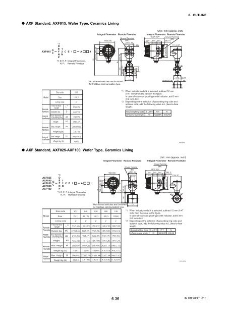
6. OUTLINE<br />
<strong>AXF</strong> Standard, <strong>AXF</strong>015, Wafer Type, Ceramics Lining<br />
<strong>AXF</strong>015 G C<br />
*3<br />
D<br />
E 1<br />
F 2 C E 1 A 1<br />
N N<br />
P<br />
*3: D, E, F; <strong>Integral</strong> <strong>Flowmeter</strong>,<br />
N, P; Remote Flowtube<br />
49(1.93)<br />
Hi<br />
73(2.87)<br />
<strong>Integral</strong> <strong>Flowmeter</strong><br />
154(6.06)<br />
Hr<br />
Remote Flowtube<br />
Ground Terminal<br />
(M4)<br />
ø86(3.38)<br />
48 (1.89)<br />
70(2.76)<br />
H1<br />
63.5(2.50)<br />
3(0.12)<br />
D<br />
Unit : mm (approx. inch)<br />
<strong>Integral</strong> <strong>Flowmeter</strong> Remote Flowtube<br />
197(7.76)* 1 Ground Terminal<br />
(M4)<br />
66* 1 51.5 51.5 28(1.1)<br />
(2.6) (2.03) (2.03)<br />
111(4.37)<br />
ø128(5.04)<br />
(ød)<br />
* No infra-red switches are furnished<br />
for Fieldbus communication type.<br />
L* 2<br />
4- ø6.2(0.24)<br />
72<br />
58<br />
(2.83)<br />
(2.28)<br />
Model<br />
Remote<br />
flowtube<br />
<strong>Integral</strong><br />
flowmeter<br />
Height<br />
Size code<br />
Size<br />
Lining code<br />
Face-to-face<br />
length<br />
Outside dia.<br />
Inner diameter of<br />
Grounding ring<br />
L *2<br />
D<br />
ød<br />
H1<br />
015<br />
15(0.5)<br />
C<br />
85(3.35)<br />
44(1.73)<br />
15(0.59)<br />
144(5.67)<br />
*1: When indicator code N is selected, subtract 12 mm<br />
(0.47 inch) from the value in the figure.<br />
In case of explosion proof type with indicator, add 5 mm<br />
(0.2 inch) to it.<br />
*2: Depending on the selection of grounding ring code and<br />
optional code, add the following value to L (face-to-face<br />
length).<br />
Grounding Ring Code S, L, H, V P, T N<br />
L(Face-to-face length) +0 +22(087) -6(0.24)<br />
Remote<br />
flowtube<br />
Max. Height<br />
Weight kg (lb)<br />
Hr<br />
268(10.55)<br />
2.3(5.1)<br />
<strong>Integral</strong><br />
flowmeter<br />
Max. Height<br />
Weight kg (lb)<br />
Hi<br />
306(12.03)<br />
4(8.8)<br />
F26.EPS<br />
<strong>AXF</strong> Standard, <strong>AXF</strong>025-<strong>AXF</strong>100, Wafer Type, Ceramics Lining<br />
<strong>AXF</strong>025<br />
<strong>AXF</strong>040<br />
G<br />
<strong>AXF</strong>050<br />
C<br />
<strong>AXF</strong>080<br />
<strong>AXF</strong>100<br />
*3<br />
D<br />
E<br />
F<br />
1<br />
2 C E 1 A 1<br />
N N<br />
P<br />
*3: D, E, F; <strong>Integral</strong> <strong>Flowmeter</strong>,<br />
N, P; Remote Flowtube<br />
49(1.93)<br />
Hi<br />
73(2.87)<br />
<strong>Integral</strong> <strong>Flowmeter</strong> Remote Flowtube<br />
Ground Terminal<br />
(M4)<br />
154(6.06)<br />
ø86(3.38)<br />
48(1.89)<br />
Hr<br />
70(2.76)<br />
Unit : mm (approx. inch)<br />
<strong>Integral</strong> <strong>Flowmeter</strong> Remote Flowtube<br />
66* 1<br />
(2.6)<br />
Ground Terminal<br />
(M4)<br />
197(7.76)* 1<br />
51.5 51.5<br />
(2.03) (2.03)<br />
H1<br />
28(1.1)<br />
111(4.37)<br />
ø128(5.04)<br />
øD<br />
(ød)<br />
Size code<br />
Model Size<br />
Lining code<br />
Face-to-face<br />
length L *2<br />
Remote<br />
Flowtube<br />
Outside dia. øD<br />
<strong>Integral</strong> Inner diameter of<br />
<strong>Flowmeter</strong> Grounding ring ød<br />
Remote<br />
Flowtube<br />
Height<br />
Max. Height<br />
Weight kg (lb)<br />
H1<br />
Hr<br />
025 040<br />
25(1) 40(1.5)<br />
C C<br />
93(3.66) 106(4.17)<br />
67.5(2.66) 86(3.39)<br />
27(1.06) 40(1.57)<br />
92(3.62) 111(4.37)<br />
216(8.50) 235(9.25)<br />
2.3(5.1) 3.2(7.0)<br />
* No infra-red switches are furnished L* 2<br />
for Fieldbus communication type.<br />
050 080 100 *1: When indicator code N is selected, subtract 12 mm (0.47<br />
inch) from the value in the figure.<br />
50(2) 80(3) 100(4)<br />
In case of explosion proof type with indicator, add 5 mm<br />
(0.2 inch) to it.<br />
C C C *2: Depending on the selection of grounding ring code and<br />
optional code, add the following value to L (face-to-face<br />
120(4.72) 160(6.30) 180(7.09) length).<br />
99(3.90) 129(5.08) 155(6.10)<br />
Grounding Ring Code S, L, H, V P, T N<br />
L(Face-to-face length) +0 +22(0.87) -6(0.24)<br />
52(2.05) 81(3.19) 98(3.86)<br />
129(5.08) 159(6.26) 184(7.24)<br />
253(9.96) 283(11.14) 308(12.13)<br />
4.1(9.0) 6.8(15.0) 9.6(21.1)<br />
<strong>Integral</strong><br />
Max. Height Hi<br />
<strong>Flowmeter</strong><br />
Weight kg (lb)<br />
254(9.98) 273(10.73) 291(11.44) 321(12.64) 346(13.62)<br />
4.0(8.8) 4.9(10.8) 5.8(12.7) 8.5(18.8) 11.3(24.9)<br />
F27.EPS<br />
6-36<br />
IM 01E20D01-01E


