

User's Manual AXF Magnetic Flowmeter Integral ... - Yokogawa
User's Manual AXF Magnetic Flowmeter Integral ... - Yokogawa
User's Manual AXF Magnetic Flowmeter Integral ... - Yokogawa

Create successful ePaper yourself
Turn your PDF publications into a flip-book with our unique Google optimized e-Paper software.
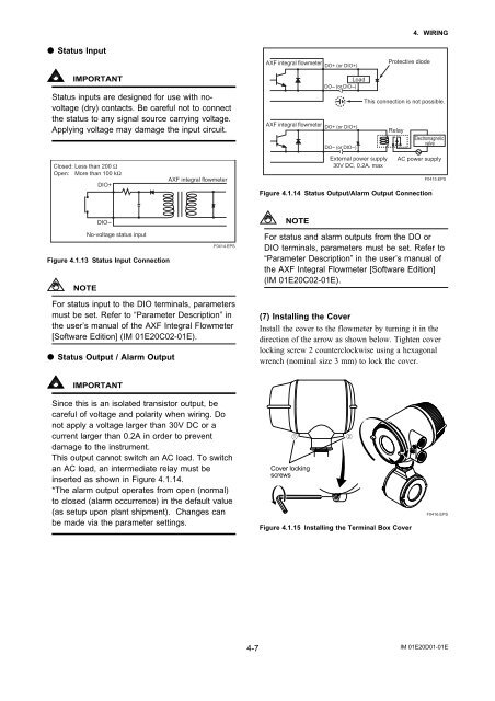
Status Input<br />
<strong>AXF</strong> integral flowmeter DO+ (or DIO+)<br />
Protective diode<br />
4. WIRING<br />
IMPORTANT<br />
Status inputs are designed for use with novoltage<br />
(dry) contacts. Be careful not to connect<br />
the status to any signal source carrying voltage.<br />
Applying voltage may damage the input circuit.<br />
Load<br />
DO- (or DIO-)<br />
<strong>AXF</strong> integral flowmeter DO+ (or DIO+)<br />
DO- (or DIO-)<br />
This connection is not possible.<br />
Relay<br />
Electromagnetic<br />
valve<br />
Closed: Less than 200 Ω<br />
Open: More than 100 kΩ<br />
DIO+<br />
<strong>AXF</strong> integral flowmeter<br />
External power supply<br />
30V DC, 0.2A. max<br />
AC power supply<br />
Figure 4.1.14 Status Output/Alarm Output Connection<br />
F0415.EPS<br />
DIO-<br />
NOTE<br />
No-voltage status input<br />
Figure 4.1.13 Status Input Connection<br />
NOTE<br />
F0414.EPS<br />
For status and alarm outputs from the DO or<br />
DIO terminals, parameters must be set. Refer to<br />
“Parameter Description” in the user’s manual of<br />
the <strong>AXF</strong> <strong>Integral</strong> <strong>Flowmeter</strong> [Software Edition]<br />
(IM 01E20C02-01E).<br />
For status input to the DIO terminals, parameters<br />
must be set. Refer to “Parameter Description” in<br />
the user’s manual of the <strong>AXF</strong> <strong>Integral</strong> <strong>Flowmeter</strong><br />
[Software Edition] (IM 01E20C02-01E).<br />
Status Output / Alarm Output<br />
(7) Installing the Cover<br />
Install the cover to the flowmeter by turning it in the<br />
direction of the arrow as shown below. Tighten cover<br />
locking screw 2 counterclockwise using a hexagonal<br />
wrench (nominal size 3 mm) to lock the cover.<br />
IMPORTANT<br />
Since this is an isolated transistor output, be<br />
careful of voltage and polarity when wiring. Do<br />
not apply a voltage larger than 30V DC or a<br />
current larger than 0.2A in order to prevent<br />
damage to the instrument.<br />
This output cannot switch an AC load. To switch<br />
an AC load, an intermediate relay must be<br />
inserted as shown in Figure 4.1.14.<br />
*The alarm output operates from open (normal)<br />
to closed (alarm occurrence) in the default value<br />
(as setup upon plant shipment). Changes can<br />
be made via the parameter settings.<br />
Cover locking<br />
screws<br />
Figure 4.1.15 Installing the Terminal Box Cover<br />
F0416.EPS<br />
4-7<br />
IM 01E20D01-01E


