Experimental and Numerical Analysis of a PCM-Supported ...
Experimental and Numerical Analysis of a PCM-Supported ...
Experimental and Numerical Analysis of a PCM-Supported ...
Create successful ePaper yourself
Turn your PDF publications into a flip-book with our unique Google optimized e-Paper software.
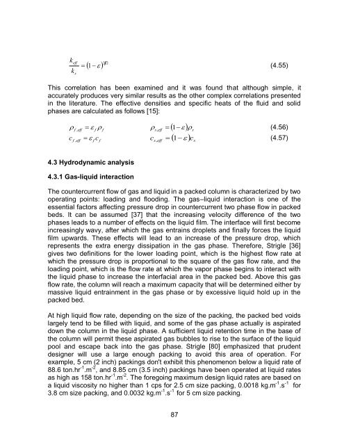
k<br />
k<br />
eff<br />
s<br />
<br />
1 3 2<br />
(4.55)<br />
This correlation has been examined <strong>and</strong> it was found that although simple, it<br />
accurately produces very similar results as the other complex correlations presented<br />
in the literature. The effective densities <strong>and</strong> specific heats <strong>of</strong> the fluid <strong>and</strong> solid<br />
phases are calculated as follows [15]:<br />
<br />
c<br />
<br />
f , eff f f<br />
s eff<br />
s<br />
c<br />
f , eff f f<br />
s<br />
<br />
,<br />
1<br />
<br />
(4.56)<br />
c s , eff<br />
1<br />
c<br />
(4.57)<br />
4.3 Hydrodynamic analysis<br />
4.3.1 Gas-liquid interaction<br />
The countercurrent flow <strong>of</strong> gas <strong>and</strong> liquid in a packed column is characterized by two<br />
operating points: loading <strong>and</strong> flooding. The gas–liquid interaction is one <strong>of</strong> the<br />
essential factors affecting pressure drop in countercurrent two phase flow in packed<br />
beds. It can be assumed [37] that the increasing velocity difference <strong>of</strong> the two<br />
phases leads to a number <strong>of</strong> effects on the liquid film. The interface will first become<br />
increasingly wavy, after which the gas entrains droplets <strong>and</strong> finally forces the liquid<br />
film upwards. These effects will lead to an increase <strong>of</strong> the pressure drop, which<br />
represents the extra energy dissipation in the gas phase. Therefore, Strigle [36]<br />
gives two definitions for the lower loading point, which is the highest flow rate at<br />
which the pressure drop is proportional to the square <strong>of</strong> the gas flow rate, <strong>and</strong> the<br />
loading point, which is the flow rate at which the vapor phase begins to interact with<br />
the liquid phase to increase the interfacial area in the packed bed. Above this gas<br />
flow rate, the column will reach a maximum capacity that will be determined either by<br />
massive liquid entrainment in the gas phase or by excessive liquid hold up in the<br />
packed bed.<br />
At high liquid flow rate, depending on the size <strong>of</strong> the packing, the packed bed voids<br />
largely tend to be filled with liquid, <strong>and</strong> some <strong>of</strong> the gas phase actually is aspirated<br />
down the column in the liquid phase. A sufficient liquid retention time in the base <strong>of</strong><br />
the column will permit these aspirated gas bubbles to rise to the surface <strong>of</strong> the liquid<br />
pool <strong>and</strong> escape back into the gas phase. Strigle [80] emphasized that prudent<br />
designer will use a large enough packing to avoid this area <strong>of</strong> operation. For<br />
example, 5 cm (2 inch) packings don't exhibit this phenomenon below a liquid rate <strong>of</strong><br />
88.6 ton.hr -1 .m -2 , <strong>and</strong> 8.85 cm (3.5 inch) packings have been operated at liquid rates<br />
as high as 158 ton.hr -1 .m -2 . The foregoing maximum design liquid rates are based on<br />
a liquid viscosity no higher than 1 cps for 2.5 cm size packing, 0.0018 kg.m -1 .s -1 for<br />
3.8 cm size packing, <strong>and</strong> 0.0032 kg.m -1 .s -1 for 5 cm size packing.<br />
87


