

Experimental and Numerical Analysis of a PCM-Supported ...
Experimental and Numerical Analysis of a PCM-Supported ...
Experimental and Numerical Analysis of a PCM-Supported ...

You also want an ePaper? Increase the reach of your titles
YUMPU automatically turns print PDFs into web optimized ePapers that Google loves.
In the second case, water heat capacity flow is decreased due to lower inlet hot<br />
water mass flow rate, while the air flow rate is maintained high. When Air flow rate<br />
has two impacts on the system performance, where the energy transfer rate through<br />
dry batches between solid <strong>and</strong> air (i.e. MEHH) increases with increasing air flow<br />
rate, both sensible <strong>and</strong> latent heat transfer at the air-liquid interface increases until<br />
reaching an optimum value <strong>of</strong> air/water mass flow ratio. Beyond this point the high<br />
sensible heat transfer rate negatively influences (i.e. comes at the expense) <strong>of</strong> the<br />
mass transfer rate at the interface. Moreover, most <strong>of</strong> the heat <strong>and</strong> mass transfer<br />
take place at the upper region <strong>of</strong> the evaporator, which causes the solid packing in<br />
the lower part <strong>of</strong> the column to be colder than the gas phase.<br />
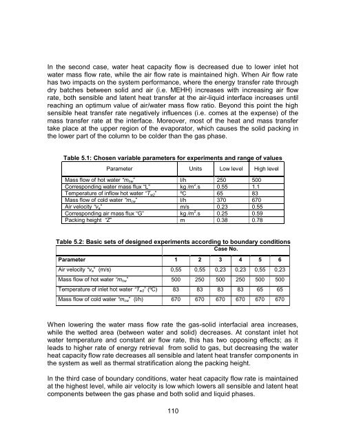
Table 5.1: Chosen variable parameters for experiments <strong>and</strong> range <strong>of</strong> values<br />
Parameter Units Low level High level<br />
Mass flow <strong>of</strong> hot water “m hw ” l/h 250 500<br />
Corresponding water mass flux “L” kg /m 2 .s 0.55 1.1<br />
Temperature <strong>of</strong> inflow hot water “T w2 ” ºC 65 83<br />
Mass flow <strong>of</strong> cold water “m cw ” l/h 370 670<br />
Air velocity “v a ” m/s 0.23 0.55<br />
Corresponding air mass flux “G” kg /m 2 .s 0.25 0.59<br />
Packing height “Z” m 0.38 0.78<br />
Table 5.2: Basic sets <strong>of</strong> designed experiments according to boundary conditions<br />
Case No.<br />
Parameter 1 2 3 4 5 6<br />
Air velocity “v a ” (m/s) 0,55 0,55 0,23 0,23 0,55 0,23<br />
Mass flow <strong>of</strong> hot water “m hw ” 500 250 500 250 500 500<br />
Temperature <strong>of</strong> inlet hot water “T w2 ” (ºC) 83 83 83 83 65 65<br />
Mass flow <strong>of</strong> cold water “m cw ” (l/h) 670 670 670 670 670 670<br />
When lowering the water mass flow rate the gas-solid interfacial area increases,<br />
while the wetted area (between water <strong>and</strong> solid) decreases. At constant inlet hot<br />
water temperature <strong>and</strong> constant air flow rate, this has two opposing effects; as it<br />
leads to higher rate <strong>of</strong> energy retrieval from solid to gas, but decreasing the water<br />
heat capacity flow rate decreases all sensible <strong>and</strong> latent heat transfer components in<br />
the system as well as thermal stratification along the packing height.<br />
In the third case <strong>of</strong> boundary conditions, water heat capacity flow rate is maintained<br />
at the highest level, while air velocity is low which lowers all sensible <strong>and</strong> latent heat<br />
components between the gas phase <strong>and</strong> both solid <strong>and</strong> liquid phases.<br />
110


