

Experimental and Numerical Analysis of a PCM-Supported ...
Experimental and Numerical Analysis of a PCM-Supported ...
Experimental and Numerical Analysis of a PCM-Supported ...

You also want an ePaper? Increase the reach of your titles
YUMPU automatically turns print PDFs into web optimized ePapers that Google loves.
The MATLAB model describes how the solar power components are combined with<br />
the desalination block in one structure to simulate the complete plant based on the<br />
coupling strategy shown in figure 4.1. The above description assumes no heat<br />
losses during fluid flow through the HDH unit. The solar collector efficiency is<br />
modelled through introduction <strong>of</strong> an empirical correlation in equation (4.84). As<br />
mentioned previously, this correlation summarily includes the heat losses through<br />
the connecting pipes with the HDH plant <strong>and</strong> the flow mal-distribution in the collector<br />
absorber. Hence rather conservative amounts <strong>of</strong> fresh water production can be<br />
expected.<br />
Control criteria <strong>and</strong> mechanisms were implemented in the simulation model to<br />
guarantee positive entropy production in the system. For instance, the solar collector<br />
should be bypassed during night or cloudy hours to avoid heat losses to ambient<br />
during these times, the outlet temperature from the solar collector must not exceed<br />
95ºC to avoid boiling <strong>of</strong> seawater <strong>and</strong> scale formation, <strong>and</strong> the inlet hot water<br />
temperature to the evaporator must not fall below the inlet cooling water temperature<br />
to the condenser. These two temperatures represent the margin for the time<br />
variation <strong>of</strong> temperature fields in the system. The inlet cooling water temperature to<br />
the condenser was assumed constant at ambient.<br />
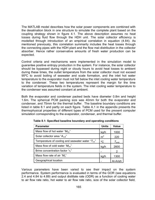
Both the evaporator <strong>and</strong> condenser packed beds have diameter 0.8m <strong>and</strong> height<br />
1.6m. The spherical <strong>PCM</strong> packing size was 40mm for both the evaporator <strong>and</strong><br />
condenser, <strong>and</strong> 75mm for the thermal buffer. The baseline boundary conditions are<br />
listed in table 8.1 <strong>and</strong> partly on each figure. Table A.1 in the appendix presents the<br />
thermophysical properties <strong>of</strong> different types <strong>of</strong> <strong>PCM</strong> used for the present computer<br />
simulation corresponding to the evaporator, condenser, <strong>and</strong> thermal buffer.<br />
Table 8.1: Specified baseline boundary <strong>and</strong> operating conditions<br />
Parameter Units Value<br />
Mass flow <strong>of</strong> hot water “M hw ” kg/h 1000<br />
Solar collector area “A coll ” m 2 220<br />
Temperature <strong>of</strong> cooling <strong>and</strong> seawater water “T cw ” ºC T amb<br />
Mass flow <strong>of</strong> cold water “M cw ” kg/h 2600<br />
Brine concentration factor “r c ” - 2<br />
Mass flow rate <strong>of</strong> air “M a ” kg/h 1300<br />
Geographical location - Al-Arish<br />
Various parameters have been varied to see their impact on the system<br />
performance. System performance is evaluated in terms <strong>of</strong> the GOR (see equations<br />
2.4 <strong>and</strong> 4.84 to 4.89) <strong>and</strong> output distillate rate (ODR) as a function <strong>of</strong> cooling water<br />
to air flow rate ratio, hot water to air flow rate ratio, size <strong>of</strong> the solar collector field,<br />
165


