- Page 1:
SSC-367 - FATIGUE TECHNOLOGY ASSESS
- Page 4 and 5:
SHIP STRUCTURF COMMllTFF The SHIP S
- Page 6 and 7:
—.--— 1. Report No. 2. Gowotnmr
- Page 8 and 9:
FATIGUE TECHNOLOGY Assessment AND D
- Page 10 and 11:
6. FATIGUE STRESS HISTORY MODELS 6,
- Page 12 and 13:
APPENDICES A. REVIEW OF OCEAN ENVIR
- Page 14 and 15:
D. VORTEX SHEDDING AVOIDANCE AND FA
- Page 16 and 17:
LIST OF FIGURES (cent.) FIGURE TITL
- Page 18 and 19:
HOT-SPOT STRESS . The hot-spot stre
- Page 20 and 21:
QA/Qc : Quality Assurance/QualityCo
- Page 22 and 23:
1. INTRODUCTION 1.1 BACKGROUND The
- Page 24 and 25:
general assessmentof fatiguewhile t
- Page 26 and 27:
2. OVERVIEW OF FATIGUE 2.1 FATIGUE
- Page 28 and 29:
2.2 FATIGUE ANALYSIS 2.2.1 Anal.vsi
- Page 30 and 31:
● Loads generated as affected by
- Page 32 and 33:
A deterministic method is sometimes
- Page 34 and 35:
1 APPLICATION OF NUMEROUS CYCLIC ST
- Page 36 and 37:
I MOBiLEANDSTATIONARY MARWE STRUCTU
- Page 38 and 39:
3. FATIGUE DESIGN AND ANALYSIS PARA
- Page 40 and 41:
and in-plane/out-of-planeangles,and
- Page 42 and 43:
the general quality of fabrication,
- Page 44 and 45:
3.2 REVIEW OF FATIGUE ANALYSIS PARA
- Page 46 and 47:
frequencies of interest, requiring
- Page 48 and 49:
● Reqular Waves in FrecjuencvDoma
- Page 50 and 51:
The finite element models of increa
- Page 52 and 53:
The stressmodel parametersdiscussed
- Page 54 and 55:
While API S-N curves are applicable
- Page 56 and 57:
DESIGN Osn40H rAnNsirsR8 FAMcA~ M P
- Page 58 and 59:
Primarily Affect .--------+’ & In
- Page 60 and 61:
MOTIONS MODEL — .—. ● ;LOADS
- Page 62 and 63:
loa 1 10 -— — — -t-i-nT 1[ -t
- Page 64 and 65:
4. GLOBAL REVIEW OF FATIGUE 4.1 APP
- Page 66 and 67: An allowable stress method, also co
- Page 68 and 69: esults of work covering assessment
- Page 70 and 71: location. Thus, the method should b
- Page 72 and 73: 1. SDectral FaticlueAnalvsis Althou
- Page 74 and 75: 2. Weibull AtIDroach The Weibull sh
- Page 76 and 77: energy about the central direction
- Page 78 and 79: Although considered to be an emergi
- Page 80 and 81: many design rules implement this ap
- Page 82 and 83: Detailed Anal.vsisMethods The detai
- Page 84 and 85: The DnV X-curve and the DEn Guidanc
- Page 86 and 87: ending restrictions. Cruciform and
- Page 88 and 89: period, are also designed tomeet th
- Page 90 and 91: incorporates inspection-strategy(Re
- Page 92 and 93: ‘Thereare numerous finite element
- Page 94 and 95: LOCATIONs oF FATIGUE CMCKS Figure 4
- Page 96 and 97: TW=’T ——— ———___ __ r
- Page 98 and 99: 1 —. — — — — -.. - .. - .
- Page 100 and 101: TOP[C U.K.DEPARTMENTOF ENERGY(OEn)
- Page 102 and 103: :1 U.K.DEPARTMENTOF ENERGY(DEn) AME
- Page 104 and 105: TOPIC U.K.DEPARTMENJOFEIWRGV(oEn) O
- Page 106 and 107: 5. FATIGUE STRESS MODELS 5.1 REVIEW
- Page 108 and 109: ● The water particle kinematicsar
- Page 110 and 111: “radiation pressure” of waves,
- Page 112 and 113: influence on the applied loading. H
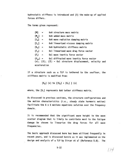
- Page 114 and 115: their function, selecting appropria
- Page 118 and 119: structure is unique and an allowabl
- Page 120 and 121: loads directly. Since the diffracti
- Page 122 and 123: typically from 0.6 to 0.8 and 1.5 t
- Page 124 and 125: therefore be defined uniformly alon
- Page 126 and 127: load analysisof adetailed three-dim
- Page 128 and 129: esponsesare required , or where con
- Page 130 and 131: either multiple stick elements (for
- Page 132 and 133: Braces may have stubs or cones, whi
- Page 134 and 135: Whatever the basis for an empirical
- Page 136 and 137: The SCF equations currently in use
- Page 138 and 139: life. During the comprehensive desi
- Page 140 and 141: ?.s I z - ]LEvE~ ~ 1,5 \ i i+ 11 Is
- Page 142 and 143: -. Figure 5-5 Comparison of Detaile
- Page 144 and 145: ( -t ) ( T-JOINT Y-JOINT ( \ I / K-
- Page 146 and 147: SMEDLEY-WORDSWORTH 0 d =— = D 600
- Page 148 and 149: Wave Records Older wave and wind in
- Page 150 and 151: In many cases wind informationmay b
- Page 152 and 153: q = 3.3 s = 0.07, for f< fm s = 0.0
- Page 154 and 155: Seasonal Variation The annual wave
- Page 156 and 157: 4. ~arpkaya spreading. (Reference 6
- Page 158 and 159: ~. \“ life of a structure,cannot
- Page 160 and 161: 6.3 TIME-DOMAIN ANALYSES Nonlinear
- Page 162 and 163: The wave environmentdefinitionsbase
- Page 164 and 165: .,..,, ....- ., ;., .. .... .- .. .
- Page 166 and 167:
● Fatiguetest data should be care
- Page 168 and 169:
assessmentis typically identifiedas
- Page 170 and 171:
damage accumulation similar to that
- Page 172 and 173:
“FabricationRestrictions Fabricat
- Page 174 and 175:
Fatigue strength of a tubular joint
- Page 176 and 177:
Current recommendations,rules and s
- Page 178 and 179:
n NB=T 1 [p=+pi Ei . ‘c where: NB
- Page 180 and 181:
(2) Damage computation does not acc
- Page 182 and 183:
DNB = (f. T/K) (2/2 U)m r (f+ 1) wh
- Page 184 and 185:
interactionof multiple fatigue crac
- Page 186 and 187:
amplitude loading and loading seque
- Page 188 and 189:
n“ CAP PASSES ROOT = * { A A 4 I
- Page 190 and 191:
It should be pointed out that the e
- Page 192 and 193:
v= flow velocity normal to the cyli
- Page 194 and 195:
8.4 METHODS OF MINIMIZING VORTEX SH
- Page 196 and 197:
Ra < S REGIME OF UNSE?ARATE~ FLOW 5
- Page 198 and 199:
ages. The designer has no control o
- Page 200 and 201:
failure data on various structures,
- Page 202 and 203:
connections, knife edge crossings,
- Page 204 and 205:
9.3.1 Fabrication Effects The fatig
- Page 206 and 207:
● Controlled Erosion An alternate
- Page 208 and 209:
after a given number of stress cycl
- Page 210 and 211:
A second pass with polishingdisc is
- Page 212 and 213:
others. Extensive analytical and ex
- Page 214 and 215:
d) Stress SDectrum Hot-spot stresse
- Page 216 and 217:
Cumulativefatiguedamagecomputations
- Page 218 and 219:
as a parametric study intended to i
- Page 220 and 221:
Additional areas requiring further
- Page 222 and 223:
GROUP Modification of Weld Profile
- Page 224 and 225:
400 ‘,, . . 350 - I I 300r [ ~ ,0
- Page 226 and 227:
TOPIC SUBJECT INVESTIGATOR COMPLETI
- Page 228 and 229:
3.1 Soyak, J. F., Caldwell, J. W.,
- Page 230 and 231:
4.12 Daidola, J.C., and Basar, N.S.
- Page 232 and 233:
5.4 Papanikolaou,A. and Zaraphoniti
- Page 234 and 235:
5.21 -”’ ” ”---”---”
- Page 236 and 237:
“7.2 Jordan, C.R., and Cochran, C
- Page 238 and 239:
7.19 Niemi, E.J., “FatigueTests o
- Page 240 and 241:
9.1 Skaar, K.T., “ContributingFac
- Page 242 and 243:
COMMllTEE ON MARINE STRUCTURES Comm
- Page 244 and 245:
U.S.Department of Transportation Un
- Page 246 and 247:
Member Agencies: United States Coas
- Page 248 and 249:
‘ METRIC CONVERSION FACTORS Appro
- Page 250 and 251:
APPENDIX A REVIEW OF OCEAN ENVIRONM
- Page 252 and 253:
The most distinctive feature-of a r
- Page 254 and 255:
s(w) = 2*(4*112) - For a “height
- Page 256 and 257:
common probability distributions, t
- Page 258 and 259:
T: v. Visually Observed Period, or
- Page 260 and 261:
The characteristic wave heights of
- Page 262 and 263:
H~ is the significantwave height, a
- Page 264 and 265:
a = 0.09, for UJ>wm The U value of
- Page 266 and 267:
H~ is the significant height, ‘m
- Page 268 and 269:
If the wind duration is less than t
- Page 270 and 271:
Sample Wave scatter Diagram s 12 +.
- Page 272 and 273:
Nm is the total number of waves in
- Page 274 and 275:
turbulence largely a function of te
- Page 276 and 277:
Applied Wind Speed Vz(t) ft/s (m/s)
- Page 278 and 279:
A.1O REFERENCES A*I Mechanics of Wa
- Page 280:
APPENDIX B REVIEW OF LINEAR SYSTEM
- Page 283 and 284:
Awhite noise function-may be used t
- Page 285 and 286:
Multiplication of the wave spectrum
- Page 287 and 288:
B.2.2.2 Response Amplitude Operator
- Page 289 and 290:
0.2.3 Wave Spectra The wave spectru
- Page 291 and 292:
9 is the acceleration of gravity in
- Page 293 and 294:
The following is..a. sample...of..a
- Page 295 and 296:
is the damping ratio,..the ratio of
- Page 297 and 298:
the set of extreme conditions, and
- Page 299 and 300:
A response scatter diagram could be
- Page 301 and 302:
2.4 2.2 2 1 ‘Sen &-”Swull$p~ctr
- Page 303 and 304:
L ‘2
- Page 305 and 306:
o Kuang (ReferenceCl) “ o Wordswo
- Page 307 and 308:
C.2 STRESS CONCENTRATION FACTOR EQU
- Page 309 and 310:
C.3 PARAMETRIC STUDY RESULTS . C.3.
- Page 311:
30. 2s , 20. 15. 10. 5. & wORDSWORT
- Page 314 and 315:
ChordSide Brace Side K-Joints SCFU
- Page 316 and 317:
Definition of Parameters, Validitv
- Page 318 and 319:
-, l— I + ?1 -— I . 4> a ,- I I
- Page 320 and 321:
Kuang SCF Computdion 1 L u UI \ f-
- Page 322 and 323:
., I , 1- out— FIano SCF m tg n I
- Page 324 and 325:
— 6 Smedley-Wordswoti SCF Computa
- Page 326 and 327:
T ln— Plan- SCF CrOwn POsltlon o
- Page 328 and 329:
C.3.l(C) Kuang Chord SCF’S for T-
- Page 330 and 331:
5 Kuang SCF Computation 4 IL u M 3
- Page 332 and 333:
C.3.l(d) Smedley-WordsworthChord SC
- Page 334 and 335:
. ,i 5 Smedley-Wordsworth SCF Compu
- Page 336 and 337:
I I K Out— Plan= SCF —— Saddl
- Page 338 and 339:
- 10 Smedley-Wordsworth SCFComputat
- Page 340 and 341:
‘\, ?v x out— Plan- SCF ——
- Page 342 and 343:
C.3.2(a) Kuang Chord SCF’S for T-
- Page 344 and 345:
KuwqSE _im T-joint In%neW UrrdSicko
- Page 346 and 347:
C.3.2(b) Smedley-HordsworthChord SC
- Page 348 and 349:
T-joint Axial SF Saddle Posiiim
- Page 350 and 351:
-— T-joint CtkuHlane ELFSaddlePci
- Page 352 and 353:
I 1 1 1 1 ~. l~o ~ ha= 1s0 : ~. ~J
- Page 354 and 355:
1 ! ! O.fi ;0.762 %841 0,769 O,= !0
- Page 356 and 357:
Ikrdwth-kdlw SF l%quiaiifm K-joint
- Page 358 and 359:
hdsmthqwdhy W Camputatim l-joint Ax
- Page 360 and 361:
Ejrnnt flkf+lane SF SaddlePmitim ~,
- Page 362 and 363:
MAXIMUM PRINCIPAL STRESS SCF = ----
- Page 364 and 365:
‘-W, .\ I Ill I : II m -,, !) .
- Page 366 and 367:
’ \./ ““’ w~”mm m ““-
- Page 368 and 369:
. . I Column L’ Longitudinal Gird
- Page 370 and 371:
C.8 Underwater Engineering Group,
- Page 372 and 373:
APPENDIX D VORTEX SHEDDING AVOIDANC
- Page 374 and 375:
a an b d f“ f ar f~ ‘bmax f~ fn
- Page 376 and 377:
D. VORTEX SHEDDING 0.1. INTRODUCTIO
- Page 378 and 379:
Vortex Shedding Frequency (f”) fv
- Page 380 and 381:
waves. When only isolated members u
- Page 382 and 383:
member’s nominal diameter and thi
- Page 384 and 385:
\Lf-! of cycles. Thus, the reduced
- Page 386 and 387:
s ; J steady current, by substituti
- Page 388 and 389:
Step 3: Obtain a new valueof 1/10 b
- Page 390 and 391:
vortex shedding will occur, i.e., V
- Page 392 and 393:
h. The fatigue life may -be modifie
- Page 394 and 395:
NOTE: The relationship given is bas
- Page 396 and 397:
CELL C7: KINEMATIC VISCOSITY = U CE
- Page 398 and 399:
COLUMN N: THE STRESS AMPLITUDE IS C
- Page 400 and 401:
D.8.3 Devices and Spoilers Devices
- Page 402 and 403:
D*9 REFERENCES D.1 King, R., “A R
- Page 404 and 405:
Fint Insmbility Rtgion I !%mmd Inat
- Page 406 and 407:
.—____ *U.S. E.P.O. :1993-343-273
- Page 410 and 411:
COMMllTEE ON MARINE STRUCTURES Comm
- Page 412:
4!! . ,—.-.,