- Page 1:
SSC-367 - FATIGUE TECHNOLOGY ASSESS
- Page 4 and 5:
SHIP STRUCTURF COMMllTFF The SHIP S
- Page 6 and 7:
—.--— 1. Report No. 2. Gowotnmr
- Page 8 and 9:
FATIGUE TECHNOLOGY Assessment AND D
- Page 10 and 11:
6. FATIGUE STRESS HISTORY MODELS 6,
- Page 12 and 13:
APPENDICES A. REVIEW OF OCEAN ENVIR
- Page 14 and 15:
D. VORTEX SHEDDING AVOIDANCE AND FA
- Page 16 and 17:
LIST OF FIGURES (cent.) FIGURE TITL
- Page 18 and 19:
HOT-SPOT STRESS . The hot-spot stre
- Page 20 and 21:
QA/Qc : Quality Assurance/QualityCo
- Page 22 and 23:
1. INTRODUCTION 1.1 BACKGROUND The
- Page 24 and 25:
general assessmentof fatiguewhile t
- Page 26 and 27:
2. OVERVIEW OF FATIGUE 2.1 FATIGUE
- Page 28 and 29:
2.2 FATIGUE ANALYSIS 2.2.1 Anal.vsi
- Page 30 and 31:
● Loads generated as affected by
- Page 32 and 33:
A deterministic method is sometimes
- Page 34 and 35:
1 APPLICATION OF NUMEROUS CYCLIC ST
- Page 36 and 37:
I MOBiLEANDSTATIONARY MARWE STRUCTU
- Page 38 and 39:
3. FATIGUE DESIGN AND ANALYSIS PARA
- Page 40 and 41:
and in-plane/out-of-planeangles,and
- Page 42 and 43:
the general quality of fabrication,
- Page 44 and 45:
3.2 REVIEW OF FATIGUE ANALYSIS PARA
- Page 46 and 47:
frequencies of interest, requiring
- Page 48 and 49:
● Reqular Waves in FrecjuencvDoma
- Page 50 and 51:
The finite element models of increa
- Page 52 and 53:
The stressmodel parametersdiscussed
- Page 54 and 55:
While API S-N curves are applicable
- Page 56 and 57:
DESIGN Osn40H rAnNsirsR8 FAMcA~ M P
- Page 58 and 59:
Primarily Affect .--------+’ & In
- Page 60 and 61:
MOTIONS MODEL — .—. ● ;LOADS
- Page 62 and 63:
loa 1 10 -— — — -t-i-nT 1[ -t
- Page 64 and 65:
4. GLOBAL REVIEW OF FATIGUE 4.1 APP
- Page 66 and 67:
An allowable stress method, also co
- Page 68 and 69:
esults of work covering assessment
- Page 70 and 71:
location. Thus, the method should b
- Page 72 and 73:
1. SDectral FaticlueAnalvsis Althou
- Page 74 and 75:
2. Weibull AtIDroach The Weibull sh
- Page 76 and 77:
energy about the central direction
- Page 78 and 79:
Although considered to be an emergi
- Page 80 and 81:
many design rules implement this ap
- Page 82 and 83:
Detailed Anal.vsisMethods The detai
- Page 84 and 85:
The DnV X-curve and the DEn Guidanc
- Page 86 and 87:
ending restrictions. Cruciform and
- Page 88 and 89:
period, are also designed tomeet th
- Page 90 and 91:
incorporates inspection-strategy(Re
- Page 92 and 93:
‘Thereare numerous finite element
- Page 94 and 95:
LOCATIONs oF FATIGUE CMCKS Figure 4
- Page 96 and 97:
TW=’T ——— ———___ __ r
- Page 98 and 99:
1 —. — — — — -.. - .. - .
- Page 100 and 101:
TOP[C U.K.DEPARTMENTOF ENERGY(OEn)
- Page 102 and 103:
:1 U.K.DEPARTMENTOF ENERGY(DEn) AME
- Page 104 and 105:
TOPIC U.K.DEPARTMENJOFEIWRGV(oEn) O
- Page 106 and 107:
5. FATIGUE STRESS MODELS 5.1 REVIEW
- Page 108 and 109:
● The water particle kinematicsar
- Page 110 and 111:
“radiation pressure” of waves,
- Page 112 and 113:
influence on the applied loading. H
- Page 114 and 115:
their function, selecting appropria
- Page 116 and 117:
hydrostatic stiffness is introduced
- Page 118 and 119:
structure is unique and an allowabl
- Page 120 and 121:
loads directly. Since the diffracti
- Page 122 and 123:
typically from 0.6 to 0.8 and 1.5 t
- Page 124 and 125:
therefore be defined uniformly alon
- Page 126 and 127:
load analysisof adetailed three-dim
- Page 128 and 129:
esponsesare required , or where con
- Page 130 and 131:
either multiple stick elements (for
- Page 132 and 133:
Braces may have stubs or cones, whi
- Page 134 and 135:
Whatever the basis for an empirical
- Page 136 and 137:
The SCF equations currently in use
- Page 138 and 139:
life. During the comprehensive desi
- Page 140 and 141:
?.s I z - ]LEvE~ ~ 1,5 \ i i+ 11 Is
- Page 142 and 143:
-. Figure 5-5 Comparison of Detaile
- Page 144 and 145:
( -t ) ( T-JOINT Y-JOINT ( \ I / K-
- Page 146 and 147:
SMEDLEY-WORDSWORTH 0 d =— = D 600
- Page 148 and 149:
Wave Records Older wave and wind in
- Page 150 and 151:
In many cases wind informationmay b
- Page 152 and 153:
q = 3.3 s = 0.07, for f< fm s = 0.0
- Page 154 and 155:
Seasonal Variation The annual wave
- Page 156 and 157:
4. ~arpkaya spreading. (Reference 6
- Page 158 and 159:
~. \“ life of a structure,cannot
- Page 160 and 161:
6.3 TIME-DOMAIN ANALYSES Nonlinear
- Page 162 and 163:
The wave environmentdefinitionsbase
- Page 164 and 165:
.,..,, ....- ., ;., .. .... .- .. .
- Page 166 and 167:
● Fatiguetest data should be care
- Page 168 and 169:
assessmentis typically identifiedas
- Page 170 and 171:
damage accumulation similar to that
- Page 172 and 173:
“FabricationRestrictions Fabricat
- Page 174 and 175:
Fatigue strength of a tubular joint
- Page 176 and 177:
Current recommendations,rules and s
- Page 178 and 179:
n NB=T 1 [p=+pi Ei . ‘c where: NB
- Page 180 and 181:
(2) Damage computation does not acc
- Page 182 and 183:
DNB = (f. T/K) (2/2 U)m r (f+ 1) wh
- Page 184 and 185:
interactionof multiple fatigue crac
- Page 186 and 187:
amplitude loading and loading seque
- Page 188 and 189:
n“ CAP PASSES ROOT = * { A A 4 I
- Page 190 and 191:
It should be pointed out that the e
- Page 192 and 193:
v= flow velocity normal to the cyli
- Page 194 and 195:
8.4 METHODS OF MINIMIZING VORTEX SH
- Page 196 and 197:
Ra < S REGIME OF UNSE?ARATE~ FLOW 5
- Page 198 and 199:
ages. The designer has no control o
- Page 200 and 201:
failure data on various structures,
- Page 202 and 203:
connections, knife edge crossings,
- Page 204 and 205:
9.3.1 Fabrication Effects The fatig
- Page 206 and 207:
● Controlled Erosion An alternate
- Page 208 and 209:
after a given number of stress cycl
- Page 210 and 211:
A second pass with polishingdisc is
- Page 212 and 213:
others. Extensive analytical and ex
- Page 214 and 215:
d) Stress SDectrum Hot-spot stresse
- Page 216 and 217:
Cumulativefatiguedamagecomputations
- Page 218 and 219:
as a parametric study intended to i
- Page 220 and 221:
Additional areas requiring further
- Page 222 and 223:
GROUP Modification of Weld Profile
- Page 224 and 225:
400 ‘,, . . 350 - I I 300r [ ~ ,0
- Page 226 and 227:
TOPIC SUBJECT INVESTIGATOR COMPLETI
- Page 228 and 229:
3.1 Soyak, J. F., Caldwell, J. W.,
- Page 230 and 231: 4.12 Daidola, J.C., and Basar, N.S.
- Page 232 and 233: 5.4 Papanikolaou,A. and Zaraphoniti
- Page 234 and 235: 5.21 -”’ ” ”---”---”
- Page 236 and 237: “7.2 Jordan, C.R., and Cochran, C
- Page 238 and 239: 7.19 Niemi, E.J., “FatigueTests o
- Page 240 and 241: 9.1 Skaar, K.T., “ContributingFac
- Page 242 and 243: COMMllTEE ON MARINE STRUCTURES Comm
- Page 244 and 245: U.S.Department of Transportation Un
- Page 246 and 247: Member Agencies: United States Coas
- Page 248 and 249: ‘ METRIC CONVERSION FACTORS Appro
- Page 250 and 251: APPENDIX A REVIEW OF OCEAN ENVIRONM
- Page 252 and 253: The most distinctive feature-of a r
- Page 254 and 255: s(w) = 2*(4*112) - For a “height
- Page 256 and 257: common probability distributions, t
- Page 258 and 259: T: v. Visually Observed Period, or
- Page 260 and 261: The characteristic wave heights of
- Page 262 and 263: H~ is the significantwave height, a
- Page 264 and 265: a = 0.09, for UJ>wm The U value of
- Page 266 and 267: H~ is the significant height, ‘m
- Page 268 and 269: If the wind duration is less than t
- Page 270 and 271: Sample Wave scatter Diagram s 12 +.
- Page 272 and 273: Nm is the total number of waves in
- Page 274 and 275: turbulence largely a function of te
- Page 276 and 277: Applied Wind Speed Vz(t) ft/s (m/s)
- Page 278 and 279: A.1O REFERENCES A*I Mechanics of Wa
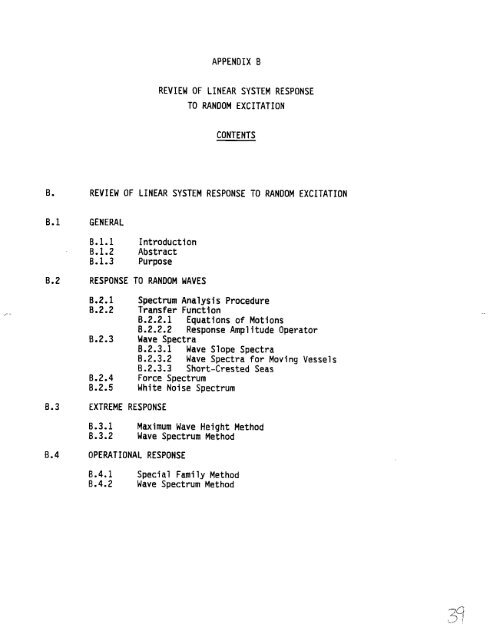
- Page 282 and 283: B. REVIEW OF LINEAR SYSTEM RESPONSE
- Page 284 and 285: the sea. By assuming thatthe respon
- Page 286 and 287: B.2.2.1 Equation of Motions By assu
- Page 288 and 289: X(w) = A*RAO(w)*cos(wt+ O(W)). When
- Page 290 and 291: [dn/dx]max= aW2/g . Squaring the eq
- Page 292 and 293: Jr 2*$ *dti= Jr 2*S*du eeee. Theref
- Page 294 and 295: The force..spectrum can be created
- Page 296 and 297: 0.3 EXTREME RESPONSE The extreme re
- Page 298 and 299: Significant response, (DA): R5 = 4.
- Page 300 and 301: From this process, the original num
- Page 302 and 303: APPENDIX C STRESS CONCENTRATIONFACT
- Page 304 and 305: c. STRESSCONCENTRATIONFACTORS. C.1
- Page 306 and 307: Ma and Tebbett also state that whil
- Page 308 and 309: C.2.2 Smedley-Wordsworth The Smedle
- Page 310 and 311: C.3.l(a) Kuang Chord SCF’S for T-
- Page 313 and 314: ChordSide BraceSide K-Joinlx SCFCX
- Page 315 and 316: Chord Sidg SCFCX= 1.7yT~(2.42 - 2.2
- Page 317 and 318: (3) Table 2 only .. (l)-~f~ ~ 0.95
- Page 319 and 320: ‘1 ——. -.— ——. . ..-—
- Page 321 and 322: 5 4 L u w 3“ 9 t o -. ii Ic Kuang
- Page 323 and 324: C.3.l(b) Smedley-Wordsworth Chord S
- Page 325 and 326: — &. 15 Smedley-Wordsworth SCF Co
- Page 327 and 328: — -. .... 5 Smedley-Wordswotih SC
- Page 329 and 330: — 5 Kuang SCF Computation 4 IL L)
- Page 331 and 332:
j K Out— ~lanq SCF ‘?’ + F .
- Page 333 and 334:
, 5 Smediey-Wordswotih SCF Computat
- Page 335 and 336:
Smedley-Wordswotih SCFComputation *
- Page 337 and 338:
C.3.l(e) Smedley-Wordsworth Chord S
- Page 339 and 340:
\ Smedley-Wordswoti SCF Computation
- Page 341 and 342:
C.3.2 Tables The Kuang and Smedley-
- Page 343 and 344:
I@q W ~tim T-juint Axial W Owd Side
- Page 345 and 346:
-- -- -- .- -- -- -- -- -- -- .- --
- Page 347 and 348:
— T-joint hid S5 Crm i%itim 1 1 1
- Page 349 and 350:
. T-joint In-PlaneSE UM P~itim ., 1
- Page 351 and 352:
— i : m ! 0.3: O*5: 0.7: o*?: 0.3
- Page 353 and 354:
Ku&W Cr@atim K-jrnntiht++laae SF M
- Page 355 and 356:
!WsA-MIEy SF bqutaticm K-joint Axia
- Page 357 and 358:
-- ..—--- ------ -- ------ ------
- Page 359 and 360:
kbrdwmii%dl~y SCFComputation ,..-,
- Page 361 and 362:
C.4 FINITE ELEMENT ANALYSES RESULTS
- Page 363 and 364:
,. .. ..-. __ _________ ._ _ ______
- Page 365 and 366:
—..—.— -.. — 7 a . LOWER HU
- Page 367 and 368:
. Loading ~ Figure C.4-4 Equivalent
- Page 369 and 370:
C.5 REFERENCES C.1 Kuang, J.G. et a
- Page 371 and 372:
(THIS PAGE INTENTIONALLY LE~ BLANK)
- Page 373 and 374:
NOMENCLATURE co CLj CLO o ‘tot DI
- Page 375 and 376:
x (THIS PAGE INTENTIONALLY LEFT BIA
- Page 377 and 378:
shedding frequency to synchronize w
- Page 379 and 380:
deflection and stability parameters
- Page 381 and 382:
a fn = ~ (EI/mi L4)% where: the mom
- Page 383 and 384:
0.3.1 In-Line Vortex Shedding . In-
- Page 385 and 386:
0.4.1 In-LineVortex Sheddinq Amplit
- Page 387 and 388:
CLO = base lift coefficient = 0.29
- Page 389 and 390:
The vortex shedding bending stress
- Page 391 and 392:
a. Depending on marine structure in
- Page 393 and 394:
c constant (See Vr reduced velocity
- Page 395 and 396:
D.7.2 Analysis for Wind-Induced Cro
- Page 397 and 398:
I . + [ (+)-L (+ - t)4] (cm4) COLUM
- Page 399 and 400:
Experiments have shown- that for a
- Page 401 and 402:
Shrouds Shrouds consist of an outer
- Page 403 and 404:
Harmonic Flow, Royal Institute of N
- Page 405 and 406:
o.: Q., 0“.. 0.1 0.1 * REGION 0 9
- Page 407:
(THIS PAGE INTENTIONALLY LEFT BIANK
- Page 411 and 412:
SHIP STRUCTURE COMMITTEE PUBLICATIO