BaseStation 3200 User Manual â 11.7.5.15 ... - Baseline Systems
BaseStation 3200 User Manual â 11.7.5.15 ... - Baseline Systems
BaseStation 3200 User Manual â 11.7.5.15 ... - Baseline Systems

You also want an ePaper? Increase the reach of your titles
YUMPU automatically turns print PDFs into web optimized ePapers that Google loves.
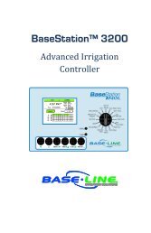
<strong>BaseStation</strong> <strong>3200</strong> Advanced Irrigation Controller <strong>Manual</strong><br />
4 –BASESTATION <strong>3200</strong> INTERFACE<br />
Review this section to get familiar with the layout of the <strong>BaseStation</strong> <strong>3200</strong> interface. This information covers the<br />
components of the front panel, the on-screen help, the features of the main screen, as well as the status colors<br />
and a brief overview of the on-screen reports.<br />
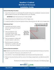
Controller Front Panel Layout<br />
(A) USB Port – The USB port is used for doing Backup<br />
and Restore operations using a USB drive (also known<br />
as a “thumb drive” or a “flash drive”). The USB port is<br />
also used for doing software updates and retrieving<br />
operation log files.<br />
(B) Display – The color display indicates the current<br />
state of the controller and is used to display<br />
programming. This display uses thin-film transistor<br />
(TFT) technology to improve image quality in outdoor<br />
conditions including direct sunlight and low light.<br />
(C) Dial – The dial is used to select the operation or<br />
programming mode of the controller.<br />
(D) Buttons – The buttons are used to select programming elements, change their values, and initiate operations<br />
like testing a zone.<br />
+ Increases the value of the highlighted field or sequences through the available options in the<br />
selected field<br />
- Decreases the value of the selected field, or sequences through the available options in the<br />
selected field<br />
NEXT<br />
PREV<br />
CLR<br />
ENTR<br />
Moves the highlighted selection to the next field on the display<br />
Moves the highlighted field selection to the previously selected field on the display<br />
Performs the function indicated at the bottom of the display, normally a “clear” or “halt”<br />
operation<br />
Saves the setting of the current selection and moves to the next item, or begins the<br />
operation. Read the text at the bottom of the display for specific details.<br />
(E) Status LEDs – These two LEDs indicate the power status of the controller and the internal status of the<br />
controller hardware. The upper light is normally ON, but it may blink when internal diagnostics are run.<br />
(F) Remote Control Port – This connector is used with the BL Commander hand-held radio remote control to<br />
operate valves while away from the controller.<br />
Page 33