

MAINTENANCE MANUAL - Meritor
MAINTENANCE MANUAL - Meritor
MAINTENANCE MANUAL - Meritor

You also want an ePaper? Increase the reach of your titles
YUMPU automatically turns print PDFs into web optimized ePapers that Google loves.
Assembly and Installation<br />
22. Install the washer and the nut the drive pinion.<br />
Prevent the drive pinion assembly from<br />
rotating by using of device or tool to hold<br />
the teeth of the helical driven gear or place<br />
wood blocks between the head of the pinion<br />
and the differential case wall. Tighten<br />
the nut to the specified torque. See Section<br />
8. Remove the holding tool or the wood<br />
blocks.<br />
23. Use an inch-pound torque wrench or a<br />
spring scale to inspect the preload of the<br />
bearings on the drive pinion.<br />
Torque Wrench Method<br />
1. Place an inch-pound (N.m) torque wrench<br />
and the correct socket in the drive pinion nut.<br />
Figure 5.16.<br />
REAR SIDE GEAR<br />
BEARING CUP<br />
CARRIER INPUT<br />
BORE<br />
Figure 5.16<br />
2. Use the torque wrench to rotate the drive pinion<br />
assembly. Inspect and record the torque<br />
level. Read while rotating the assembly. Record<br />
the dynamic or rotating torque not the<br />
starting torque.<br />
3. The preload of the drive pinion bearings must<br />
be within the following limits.<br />
• For new pinion bearings: 5-45 lb-in (0.56-<br />
5.08 N.m) rotational torque .<br />
• For used pinion bearings: 10-30 lb-in (1.13-<br />
3.39 N.m ) rotational torque .<br />
• If the preload is not within the specified limits,<br />
remove and replace the spacer between<br />
the outer bearing cone and the helical driven<br />
gear. See the procedure below:<br />
• To decrease the preload, install a thicker<br />
spacer.<br />
• To increase the preload, install a thinner spacer.<br />
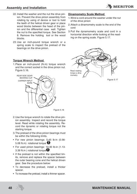
Dinamometry Scale Method<br />
1. Wind a cord around the washer under the nut<br />
of the drive pinion<br />
2. Attach a dinamometry scale to the end of the<br />
cord<br />
3. Pull the dynamometry scale and cord in a<br />
horizontal direction while looking at the reading<br />
on the spring scale. Figure 5.17.<br />
Read rotating<br />
torque a dinamometry<br />
Figure 5.17<br />
48 <strong>MAINTENANCE</strong> <strong>MANUAL</strong>


