

MAINTENANCE MANUAL - Meritor
MAINTENANCE MANUAL - Meritor
MAINTENANCE MANUAL - Meritor

Create successful ePaper yourself
Turn your PDF publications into a flip-book with our unique Google optimized e-Paper software.
Driver-Controlled Main Differential Lock<br />
10.Install the manual engaging capscrew into<br />
the threaded hole in the center of the cylinder<br />
cover or cylinder.<br />
WARNING<br />
THERE WILL BE A SMALL AMOUNT OF<br />
SPRING RESISTANCE FELT WHEN YOU TURN<br />
IN THE <strong>MANUAL</strong> ENGAGING CAPSCREW. IF A<br />
HIGH RESISTANCE IS FELT BEFORE REACH-<br />
ING THE LOCkED OR ENGAGED POSITION,<br />
STOP TURNING THE CAPSCREW, OR THE<br />
COVER, FORk AND CAPSCREW THREADS<br />
WILL BE DAMAGED.<br />
11. Turn the manual adjusting capscrew to the<br />
right until the head is approximately 0.25-inch<br />
(6 mm) from the cylinder cover. Do not turn<br />
the capscrew beyond its normal stop.<br />
A high resistance on the capscrew indicates<br />
that the splines of the shift collar and the differential<br />
case half are not aligned or engaged. To<br />
align the splines, use the following procedure.<br />
A. Rotate the left-hand wheel to align the splines<br />
of the shift collar and case half while you turn in<br />
the manual engaging capscrews.<br />
B. When the normal amount of spring resistance<br />
is again felt on the capscrew, the<br />
splines are engaged. Continue to turn in the<br />
manual engaging capscrew until the head<br />
is approximately 0.25-inch (6 mm) from the<br />
cylinder cover. The capscrew is now in the<br />
service position and the main differential lock<br />
is completely engaged.<br />
12. Remove the differential from the axle housing.<br />
See the Section 3.<br />
13.Release the differential lock by removing<br />
the manual engaging capscrew and seal<br />
from the cylinder cover or cylinder.<br />
Auxiliary Air Supply Method<br />
1. Park the vehicle on a level surface. Block the<br />
wheels to prevent the vehicle from moving.<br />
2.Use a jack to raise the left-hand wheel of the<br />
drive axle. Place a safety stand under the lefthand<br />
axle housing leg to support the vehicle in<br />
the raised position.<br />
3. Remove the drain plug from the bottom of the<br />
housing and drain the lubricant.<br />
4. Disconnect the driveline from the input fork.<br />
5. Disconnect the vehicle air line from the interaxle<br />
differential and main differential lock actuator<br />
assemblies.<br />
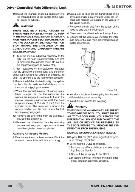
Figure 6.4<br />
6. Install a suitable air line coupling into the main<br />
differential actuator assembly.<br />
7. Install the air line into the coupling.<br />
WARNING<br />
WHEN YOU USE AN AUXILIARY AIR SUPPLY<br />
TO ENGAGE THE DCDL, YOU MUST SUPPLY<br />
AIR TO THE DCDL UNTIL YOU REMOVE THE<br />
DIFFERENTIAL. DO NOT DISCONNECT THE<br />
AIR LINE OR REDUCE AIR PRESSURE TO<br />
THE DCDL BEFORE YOU REMOVE THE DIF-<br />
FERENTIAL FROM THE HOUSING.<br />
DAMAGE TO COMPONENTS CAN RESULT.<br />
8.Supply 120 psi (827 kPa) regulated air pressure<br />
through the air line.<br />
9. Verify that the DCDL is engaged.<br />
10.Remove the differential from the axle housing.<br />
See the Section 3.<br />
11. Shut-off the air supply to the DCDL..<br />
12. Disconnect the air line from the main differential<br />
actuator assembly coupling.<br />
88 <strong>MAINTENANCE</strong> <strong>MANUAL</strong><br />
NUBS


