

MAINTENANCE MANUAL - Meritor
MAINTENANCE MANUAL - Meritor
MAINTENANCE MANUAL - Meritor

You also want an ePaper? Increase the reach of your titles
YUMPU automatically turns print PDFs into web optimized ePapers that Google loves.
A. Apply axle lubricant to the inner bore of the<br />
bearing cage or the outer diameter of the new<br />
oil seal.<br />
CAUTION<br />
HOLD THE SEAL ONLY ON THE OUTER DI-<br />
AMETER. DO NOT TOUCH THE LIPS IN THE<br />
INNER DIAMETER OF THE SEAL. IF YOU<br />
TOUCH THE LIPS ON THE INNER DIAMETER<br />
OF THE SEAL, YOU WILL CONTAMINATE THE<br />
LIPS AND COULD CAUSE A LEAk BETWEEN<br />
THE SHAFT AND THE SEAL.<br />
B. Place the oil seal into the bearing cage so<br />
that the flange is parallel to the top of the<br />
cage.<br />
C. Use a press and driver or flat metal plate<br />
to install the oil seal into the bearing cage.<br />
Figure 5.67.<br />
CAUTION<br />
DO NOT APPLY PRESSURE AFTER THE<br />
SEAL FLANGE TOUCHES THE TOP OF THE<br />
CAGE OR YOU WILL DAMAGE THE CAGE.<br />
<strong>MAINTENANCE</strong> <strong>MANUAL</strong><br />
Figure 5.67<br />
D. Apply pressure until the metal flange of the<br />
seal is seated to the top of the cage.<br />
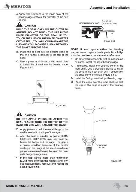
E. After the seal is installed, a gap of 0.015-<br />
0.030-inch (0.381-0.762 mm) can exist between<br />
the flange and the cage. The gap is<br />
a normal condition because of the flexible<br />
coating on the flange of the seal. Use a feeler<br />
gauge to measure the gap between the complete<br />
flange-to-cage area.<br />
• If the gap varies more than 0.010-inch<br />
(0.254 mm) between the highest and lowest<br />
measurement, remove and reseat the<br />
seal. Figure 5.68.<br />
MEASURING SEAL GAP<br />
Assembly and Installation<br />
0.015-0.03”<br />
(0.381-0.762 MM)<br />
Figure 5.68<br />
NOTE: If you replace either the bearing<br />
cap or cone, replace both parts in a fullymatched<br />
set from the same manufacturer.<br />
4. On differential assembly that do not use an<br />
oil pump, install the input bearing cage.<br />
A. If removed, install the bearing cone in the<br />
input shaft. Use a press and sleeve to install<br />
the cone in the input shaft until it bottoms on<br />
the shoulder of the shaft. Figure 5.69.<br />
B. Install the O-ring onto the input bearing cage.<br />
C. Place the cage over the input shaft so that<br />
the cap in the cage is against the bearing<br />
cone.<br />
PRESS<br />
SLEEVE<br />
BEARING<br />
CONE<br />
Figure 5.69<br />
65


