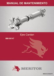
MAINTENANCE MANUAL - Meritor
MAINTENANCE MANUAL - Meritor
MAINTENANCE MANUAL - Meritor
Create successful ePaper yourself
Turn your PDF publications into a flip-book with our unique Google optimized e-Paper software.
Assembly and Installation<br />
2. Inspect the shift shaft for damage. If necessary,<br />
replace the shift shaft.<br />
3. If removed, install new O-rings in the<br />
groove in the shift shaft, into the groove in<br />
the shift cylinder and onto the piston.<br />
4. Lubricate the bore of the shift cylinder with<br />
axle lubricant.<br />
5. Install the piston in the shift cylinder.<br />
6. Insert the shift shaft in the piston and<br />
shift cylinder assembly.<br />
7. Install the small snap ring that fastens the<br />
piston in the shift shaft.<br />
8. Install the spring in the piston bore.<br />
9. Install the gasket so that the tab on the<br />
gasket is under the right capscrew bore.<br />
10. Place the shift cover in the shift cylinder<br />
housing. Install two capscrews and washers<br />
to fasten the shift cover to the cylinder.<br />
11. Install the assembly into the differential so that<br />
the shift shaft is in the bore of the shift fork.<br />
12. Install the “E” clip onto the shift shaft slot in<br />
front of the shift fork.<br />
13. Install the capscrews and washers that fasten<br />
the assembly to the differential case. Tighten<br />
the capscrews to 7-12 lb-ft (10-16 N.m).<br />
NOTE:<br />
The adjusting screw is set to the specified<br />
distance after the input shaft assembly is<br />
installed.<br />
14. Install the adjusting bolt and jam nut.<br />
Assembly Input Shaft, Bearing Cage,<br />
Oil Pump and Inter-Axle Differential.<br />
1. Apply axle lubricant to the parts as they are<br />
being assembled. Figure5.65.<br />
1 - PRESSURE RELIEF<br />
VALVE ASSEMBLY<br />
2 - OIL SEAL<br />
3 - BEARING CAGE<br />
4 - O-RING<br />
5 - BEARING CP<br />
6 - BEARING CONE<br />
7 - O-RING<br />
8 - OIL BAFFLE - UNITS<br />
WITHOUT OIL PUMP<br />
9 - WASHER<br />
10 - CAPSCREW<br />
11 - OIL PUMP - UNITS WITH<br />
OIL PUMP<br />
12 - INPUT SHAFT<br />
13 - THRUST WASHER<br />
14 - HELICAL DRIVE GEAR<br />
15 - INTE-AXLE DIFFERENTIAL<br />
16 - SNAP RING<br />
Figure 5.65<br />
2. If removed, install the bearing cap in the input<br />
bearing cage. Use a press and a sleeve to<br />
install the cap into the cage. The cap is correctly<br />
installed when the bottom of the cap is<br />
fully seated in the cage bore<br />
3. If removed, install a new oil seal into the input<br />
bearing cage.<br />
• For unitized pinion seals, look the unitized<br />
pinion seal installation procedure in this section<br />
and then proceed to Step 4. Figure5.66.<br />
• For all other seals, look the following instructions.<br />
INTEGRATED<br />
SEAL<br />
TRIPLE-LIP SEAL WITH<br />
POSE FEATURE<br />
RIPLE-LIP SEAL<br />
WITHOUT POSE<br />
FEATURE<br />
Figure 5.66<br />
64 <strong>MAINTENANCE</strong> <strong>MANUAL</strong>


