

MAINTENANCE MANUAL - Meritor
MAINTENANCE MANUAL - Meritor
MAINTENANCE MANUAL - Meritor

Create successful ePaper yourself
Turn your PDF publications into a flip-book with our unique Google optimized e-Paper software.
NOTE:<br />
Some models use silastic seal instead of<br />
the flat washer in Step E. Also, a roll pin is<br />
installed in the shift shaft and is used as a<br />
stop for the shift shaft spring. It is not necessary<br />
to remove this roll pin during a normal<br />
disassembly.<br />
E. Remove the shift shaft spring and flat washer.<br />
F. Remove the shift fork and continue with Step<br />
11 in the previous procedure.<br />
CAPSCREW AND WASH-<br />
ER, FOUR CORNERS<br />
DCDL Installation<br />
Differential Shift Assembly<br />
WARNING<br />
When you apply some silicone gasket materials, a<br />
small a mount of acid vapor is present. To prevent<br />
serious personal injury, ensure that the work area<br />
is well-ventilated. Read the manufacturer’s instructions<br />
before using a silicone gasket material, then<br />
carefully follow the instructions. If a silicone gasket<br />
material gets into your eyes, follow the manufacturer’s<br />
emergency procedures. Have your eyes<br />
checked by a physician as soon as possible.<br />
Take care when you use Loctite® adhesive to<br />
avoid serious personal injury. Read the manufacturer’s<br />
instructions before using this product. Follow<br />
the instructions carefully to prevent irritation to<br />
the eyes and skin.<br />
<strong>MAINTENANCE</strong> <strong>MANUAL</strong><br />
TAPA, JUNTA DE COBRE<br />
debajo de la tapa - sólo<br />
Serie 160<br />
Figure 6.14<br />
Driver-Controlled Main Differential Lock<br />
Threaded DCDL Shift Assembly.<br />
Install the differential shift assembly after the differential<br />
is assembled and the gear and bearing<br />
adjustments are made. The Threaded DCDL shift<br />
assembly is shown in Figure 6.15<br />
THREADED VERSION UNLOCKED<br />
SHIFT SHAFT AND<br />
SPRING<br />
RING GEAR<br />
Figure 6.15<br />
ELETRIC CONNECTION<br />
FOR SENSOR<br />
SHIFT FORK<br />
POSITION FIXING<br />
SCREW GEAR<br />
CILYNDER<br />
O’RING<br />
PISTON<br />
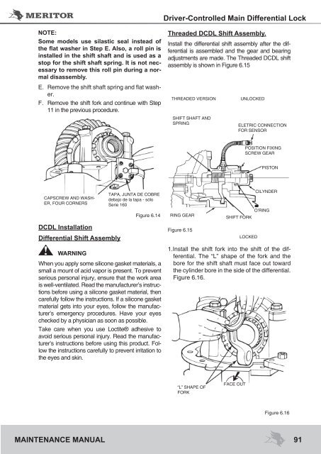
1.Install the shift fork into the shift of the differential.<br />
The “L” shape of the fork and the<br />
bore for the shift shaft must face out toward<br />
the cylinder bore in the side of the differential.<br />
Figure 6.16.<br />
“L” SHAPE OF<br />
FORK<br />
FACE OUT<br />
LOCKED<br />
Figure 6.16<br />
91


