Radiography in Modern Industry - Kodak
Radiography in Modern Industry - Kodak
Radiography in Modern Industry - Kodak

Create successful ePaper yourself
Turn your PDF publications into a flip-book with our unique Google optimized e-Paper software.
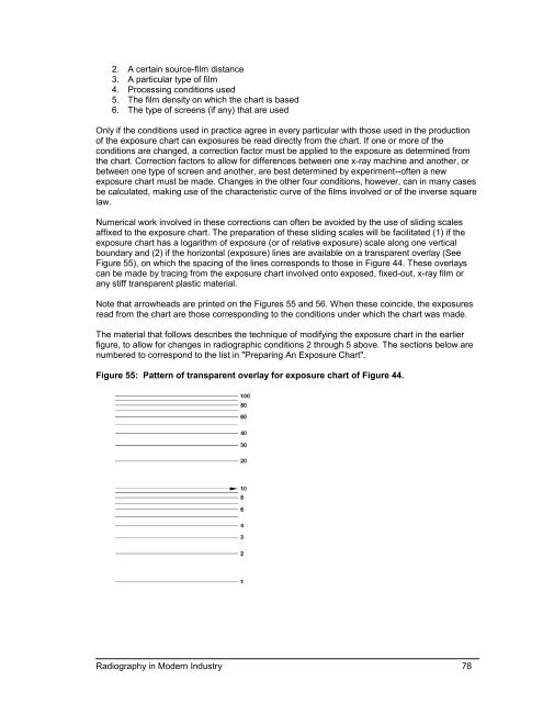
2. A certa<strong>in</strong> source-film distance3. A particular type of film4. Process<strong>in</strong>g conditions used5. The film density on which the chart is based6. The type of screens (if any) that are usedOnly if the conditions used <strong>in</strong> practice agree <strong>in</strong> every particular with those used <strong>in</strong> the productionof the exposure chart can exposures be read directly from the chart. If one or more of theconditions are changed, a correction factor must be applied to the exposure as determ<strong>in</strong>ed fromthe chart. Correction factors to allow for differences between one x-ray mach<strong>in</strong>e and another, orbetween one type of screen and another, are best determ<strong>in</strong>ed by experiment--often a newexposure chart must be made. Changes <strong>in</strong> the other four conditions, however, can <strong>in</strong> many casesbe calculated, mak<strong>in</strong>g use of the characteristic curve of the films <strong>in</strong>volved or of the <strong>in</strong>verse squarelaw.Numerical work <strong>in</strong>volved <strong>in</strong> these corrections can often be avoided by the use of slid<strong>in</strong>g scalesaffixed to the exposure chart. The preparation of these slid<strong>in</strong>g scales will be facilitated (1) if theexposure chart has a logarithm of exposure (or of relative exposure) scale along one verticalboundary and (2) if the horizontal (exposure) l<strong>in</strong>es are available on a transparent overlay (SeeFigure 55), on which the spac<strong>in</strong>g of the l<strong>in</strong>es corresponds to those <strong>in</strong> Figure 44. These overlayscan be made by trac<strong>in</strong>g from the exposure chart <strong>in</strong>volved onto exposed, fixed-out, x-ray film orany stiff transparent plastic material.Note that arrowheads are pr<strong>in</strong>ted on the Figures 55 and 56. When these co<strong>in</strong>cide, the exposuresread from the chart are those correspond<strong>in</strong>g to the conditions under which the chart was made.The material that follows describes the technique of modify<strong>in</strong>g the exposure chart <strong>in</strong> the earlierfigure, to allow for changes <strong>in</strong> radiographic conditions 2 through 5 above. The sections below arenumbered to correspond to the list <strong>in</strong> "Prepar<strong>in</strong>g An Exposure Chart".Figure 55: Pattern of transparent overlay for exposure chart of Figure 44.<strong>Radiography</strong> <strong>in</strong> <strong>Modern</strong> <strong>Industry</strong> 78