a radiographic sensitivity level of 2-2T. The first symbol (2) <strong>in</strong>dicates that the penetrameter shallbe 2 percent of the thickness of the specimen; the second (2T) <strong>in</strong>dicates that the hole hav<strong>in</strong>g adiameter twice the penetrameter thickness shall be visible on the f<strong>in</strong>ished radiograph. The qualitylevel 2-2T is probably the one most commonly specified for rout<strong>in</strong>e radiography. However, criticalcomponents may require more rigid standards, and a level of 1-2T or 1-1T may be required. Onthe other hand, the radiography of less critical specimens may be satisfactory if a quality level of2-4T or 4-4T is achieved. The more critical the radiographic exam<strong>in</strong>ation--that is, the higher thelevel of radiographic sensitivity required--the lower the numerical designation for the quality level.Some sections of the ASME (American Society of Mechanical Eng<strong>in</strong>eers) Boiler and PressureVessel Code require a penetrameter similar <strong>in</strong> general to the ASTM penetrameter. It conta<strong>in</strong>sthree holes, one of which is 2T <strong>in</strong> diameter, where T is the penetrameter thickness. Customarily,the other two holes are 3T and 4T <strong>in</strong> diameter, but other sizes may be used. M<strong>in</strong>imum hole size is1/6 <strong>in</strong>ch. Penetrameters 0.010 <strong>in</strong>ch, and less, <strong>in</strong> thickness also conta<strong>in</strong> a slit 0.010-<strong>in</strong>ch wide and1/4 <strong>in</strong>ch long. Each is identified by a lead number designat<strong>in</strong>g the thickness <strong>in</strong> thousandths of an<strong>in</strong>ch.Equivalent Penetrameter SensitivityIdeally, the penetrameter should be made of the same material as the specimen. However, this issometimes impossible because of practical or economic difficulties. In such cases, thepenetrameter may be made of a radiographically similar material--that is, a material hav<strong>in</strong>g thesame radiographic absorption as the specimen, but one of which it is easier to makepenetrameters. Tables of radiographically equivalent materials have been published where<strong>in</strong>materials hav<strong>in</strong>g similar radiographic absorptions are arranged <strong>in</strong> groups. In addition, apenetrameter made of a particular material may be used <strong>in</strong> the radiography of materials hav<strong>in</strong>ggreater radiographic absorption. In such a case, there is a certa<strong>in</strong> penalty on the radiographictesters, because they are sett<strong>in</strong>g for themselves more rigid radiographic quality standards thanare actually required. The penalty is often outweighed, however, by avoidance of the problems ofobta<strong>in</strong><strong>in</strong>g penetrameters of an unusual material or one of which it is difficult to makepenetrameters.In some cases, the materials <strong>in</strong>volved do not appear <strong>in</strong> published tabulations. Under thesecircumstances the comparative radiographic absorption of two materials may be determ<strong>in</strong>edexperimentally. A block of the material under test and a block of the material proposed forpenetrameters, equal <strong>in</strong> thickness to the part be<strong>in</strong>g exam<strong>in</strong>ed, can be radiographed side by sideon the same film with the technique to be used <strong>in</strong> practice. If the density under the proposedpenetrameter materials is equal to or greater than the density under the specimen material, thatproposed material is suitable for fabrication of penetrameters.In practically all cases, the penetrameter is placed on the source side of the specimen--that is, <strong>in</strong>the least advantageous geometric position. In some <strong>in</strong>stances, however, this location for thepenetrameter is not feasible. An example would be the radiography of a circumferential weld <strong>in</strong> along tubular structure, us<strong>in</strong>g a source positioned with<strong>in</strong> the tube and film on the outer surface. Insuch a case a "film-side" penetrameter must be used. Some codes specify the film-sidepenetrameter that is equivalent to the source-side penetrameter normally required. When such aspecification is not made, the required film-side penetrameter may be found experimentally. In theexample above, a short section of tube of the same dimensions and materials as the item undertest would be used to demonstrate the technique. The required penetrameter would be used onthe source side, and a range of penetrameters on the film side. If the penetrameter on the sourceside <strong>in</strong>dicated that the required radiographic sensitivity was be<strong>in</strong>g achieved, the image of thesmallest visible penetrameter hole <strong>in</strong> the film-side penetrameters would be used to determ<strong>in</strong>e thepenetrameter and the hole size to be used on the production radiograph.Sometimes the shape of the part be<strong>in</strong>g exam<strong>in</strong>ed precludes plac<strong>in</strong>g the penetrameter on the part.When this occurs, the penetrameter may be placed on a block of radiographically similar material<strong>Radiography</strong> <strong>in</strong> <strong>Modern</strong> <strong>Industry</strong> 92
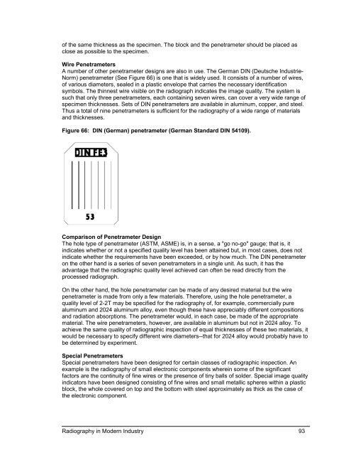
of the same thickness as the specimen. The block and the penetrameter should be placed asclose as possible to the specimen.Wire PenetrametersA number of other penetrameter designs are also <strong>in</strong> use. The German DIN (Deutsche Industrie-Norm) penetrameter (See Figure 66) is one that is widely used. It consists of a number of wires,of various diameters, sealed <strong>in</strong> a plastic envelope that carries the necessary identificationsymbols. The th<strong>in</strong>nest wire visible on the radiograph <strong>in</strong>dicates the image quality. The system issuch that only three penetrameters, each conta<strong>in</strong><strong>in</strong>g seven wires, can cover a very wide range ofspecimen thicknesses. Sets of DIN penetrameters are available <strong>in</strong> alum<strong>in</strong>um, copper, and steel.Thus a total of n<strong>in</strong>e penetrameters is sufficient for the radiography of a wide range of materialsand thicknesses.Figure 66: DIN (German) penetrameter (German Standard DIN 54109).Comparison of Penetrameter DesignThe hole type of penetrameter (ASTM, ASME) is, <strong>in</strong> a sense, a "go no-go" gauge; that is, it<strong>in</strong>dicates whether or not a specified quality level has been atta<strong>in</strong>ed but, <strong>in</strong> most cases, does not<strong>in</strong>dicate whether the requirements have been exceeded, or by how much. The DIN penetrameteron the other hand is a series of seven penetrameters <strong>in</strong> a s<strong>in</strong>gle unit. As such, it has theadvantage that the radiographic quality level achieved can often be read directly from theprocessed radiograph.On the other hand, the hole penetrameter can be made of any desired material but the wirepenetrameter is made from only a few materials. Therefore, us<strong>in</strong>g the hole penetrameter, aquality level of 2-2T may be specified for the radiography of, for example, commercially purealum<strong>in</strong>um and 2024 alum<strong>in</strong>um alloy, even though these have appreciably different compositionsand radiation absorptions. The penetrameter would, <strong>in</strong> each case, be made of the appropriatematerial. The wire penetrameters, however, are available <strong>in</strong> alum<strong>in</strong>um but not <strong>in</strong> 2024 alloy. Toachieve the same quality of radiographic <strong>in</strong>spection of equal thicknesses of these two materials, itwould be necessary to specify different wire diameters--that for 2024 alloy would probably have tobe determ<strong>in</strong>ed by experiment.Special PenetrametersSpecial penetrameters have been designed for certa<strong>in</strong> classes of radiographic <strong>in</strong>spection. Anexample is the radiography of small electronic components where<strong>in</strong> some of the significantfactors are the cont<strong>in</strong>uity of f<strong>in</strong>e wires or the presence of t<strong>in</strong>y balls of solder. Special image quality<strong>in</strong>dicators have been designed consist<strong>in</strong>g of f<strong>in</strong>e wires and small metallic spheres with<strong>in</strong> a plasticblock, the whole covered on top and the bottom with steel approximately as thick as the case ofthe electronic component.<strong>Radiography</strong> <strong>in</strong> <strong>Modern</strong> <strong>Industry</strong> 93
- Page 1 and 2:
RadiographyinModernIndustry
- Page 3 and 4:
RadiographyinModernIndustryFOURTH E
- Page 5 and 6:
ContentsIntroduction...............
- Page 7 and 8:
Chapter 1: The Radiographic Process
- Page 9 and 10:
Intensifying ScreensX-ray and other
- Page 11 and 12:
makes it a very suitable material f
- Page 13 and 14:
Figure 6: Typical voltage waveforms
- Page 15 and 16:
Table I - Typical X-ray Machines an
- Page 17 and 18:
The wavelengths (or energies of rad
- Page 19 and 20:
Table III - Industrial Gamma-Ray So
- Page 21 and 22:
1. The source of light should be sm
- Page 23 and 24:
B and H in the Figure 13 show the e
- Page 25 and 26:
Figure 14: Geometric construction f
- Page 27 and 28:
Figure 17: Pinhole pictures of the
- Page 29 and 30:
The kilovoltage applied to the x-ra
- Page 31 and 32:
Figure 21: Schematic diagram of som
- Page 33 and 34:
kind of material radiographed, the
- Page 35 and 36:
instance, the kilovoltage may be fi
- Page 37 and 38:
The technique need not be limited t
- Page 39 and 40:
Chapter 5: Radiographic ScreensWhen
- Page 41 and 42: Contact between the film and the le
- Page 43 and 44: Figure 29: The number of electrons
- Page 45 and 46: lead foil screens ran be retained w
- Page 47 and 48: Figure 33: The sharpness of the rad
- Page 49 and 50: Figure 34: Low density (right) is a
- Page 51 and 52: such as a wall or floor, on the fil
- Page 53 and 54: from this source. Since scatter als
- Page 55 and 56: A filter reduces excessive subject
- Page 57 and 58: Definite rules as to filter thickne
- Page 59 and 60: 0.010-inch front screen of value be
- Page 61 and 62: Example: Suppose that with a given
- Page 63 and 64: If the milliamperage remains consta
- Page 65 and 66: espectively. In other words, a cons
- Page 67 and 68: Any given exposure chart applies to
- Page 69 and 70: Figure 46: Typical gamma-ray exposu
- Page 71 and 72: where the slope of the characterist
- Page 73 and 74: Figure 49: Characteristic curves of
- Page 75 and 76: Figure 51: Characteristic curve of
- Page 77 and 78: Nomogram MethodsIn Figure 54, the s
- Page 79 and 80: Figure 56: Transparent overlay posi
- Page 81 and 82: Figure 58: Overlay positioned so as
- Page 83 and 84: The problem of radiographing a part
- Page 85 and 86: Figure 62: System of lines drawn on
- Page 87 and 88: Chapter 8: Radiographic Image Quali
- Page 89 and 90: Film contrast refers to the slope (
- Page 91: Hole Type PenetrametersThe common p
- Page 95 and 96: Chapter 9: Industrial X-ray FilmsMo
- Page 97 and 98: Figure 70 indicates the direction t
- Page 99 and 100: the lead letters on a radiation-abs
- Page 101 and 102: Therefore, protection requirements
- Page 103 and 104: 5. Avoid pressure damage caused by
- Page 105 and 106: Paddles or plunger-type agitators a
- Page 107 and 108: slow, and the development time reco
- Page 109 and 110: ubbles make their way to the surfac
- Page 111 and 112: When development is complete, the f
- Page 113 and 114: soften considerably with prolonged
- Page 115 and 116: Figure 77: The roller transport sys
- Page 117 and 118: Rapid Access to Processed Radiograp
- Page 119 and 120: Figure 78: Film-feeding procedures
- Page 121 and 122: Chapter 11: Process ControlUsers of
- Page 123 and 124: 3. Age of the developer replenisher
- Page 125 and 126: Figure 80: Control chart below for
- Page 127 and 128: DiscussionDensitometric data and pr
- Page 129 and 130: Figure 82: Plan of a manual x-ray p
- Page 131 and 132: Figure 83: A schematic diagram of a
- Page 133 and 134: loading-bench activities are carrie
- Page 135 and 136: KODAK Quinone-Thiosulfate Intensifi
- Page 137 and 138: Methylene-Blue MethodTwo variations
- Page 139 and 140: KODAK Hypo Test Solution HT-2Avoird
- Page 141 and 142: In summary, use of the test papers
- Page 143 and 144:
narrow angle would be very thick, e
- Page 145 and 146:
When radiation passes through a spe
- Page 147 and 148:
Figure 89: Demonstration of the eff
- Page 149 and 150:
Figure 90: The amount of gamma radi
- Page 151 and 152:
The radiograph exposed in the right
- Page 153 and 154:
To illustrate, let us assume that t
- Page 155 and 156:
Figure 95: High-speed x-ray picture
- Page 157 and 158:
Figure 97: Two methods of neutron r
- Page 159 and 160:
Duplicating RadiographsSimultaneous
- Page 161 and 162:
Sometimes, as when sets of referenc
- Page 163 and 164:
PhotofluorographyIn photofluorograp
- Page 165 and 166:
discontinuities or of segregation i
- Page 167 and 168:
from the camera or by reaching down
- Page 169 and 170:
Figure 106: Schematic diagram of th
- Page 171 and 172:
valuable technique, for instance, i
- Page 173 and 174:
The position of the spots is determ
- Page 175 and 176:
Powder Diffraction File, Internatio
- Page 177 and 178:
Processing TechniquesRadiographs on
- Page 179 and 180:
Since this formula applies only to
- Page 181 and 182:
such that it does not distort the i
- Page 183 and 184:
Figure 113: A: Representation of a
- Page 185 and 186:
Figure 115: Characteristic curve of
- Page 187 and 188:
film fairly well. If high densities
- Page 189 and 190:
Density = 1.5 Density = 2.5Film Rel
- Page 191 and 192:
In most industrial radiography, the
- Page 193 and 194:
e noted here. Although the average
- Page 195 and 196:
Chapter 17: Film Graininess; Signal
- Page 197 and 198:
The ratio of signal to noise has a
- Page 199 and 200:
Chapter 18: The Photographic Latent
- Page 201 and 202:
Thus, the change that makes an expo
- Page 203 and 204:
Figure 130: Stages in the developme
- Page 205 and 206:
electrons by successive Compton int
- Page 207 and 208:
Development is essentially a chemic
- Page 209 and 210:
Chapter 19: ProtectionOne of the mo
- Page 211 and 212:
duct is brought into the x-ray room