Intel® Extended Memory 64 Technology Software Developer's Guide
Intel® Extended Memory 64 Technology Software Developer's Guide
Intel® Extended Memory 64 Technology Software Developer's Guide

Create successful ePaper yourself
Turn your PDF publications into a flip-book with our unique Google optimized e-Paper software.
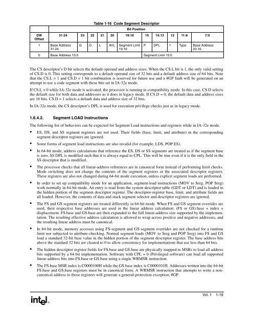
DWOffset1 Base Address31:24Table 1-16 Code Segment DescriptorBit Position31:24 23 22 21 20 19:16 15 14:13 12 11:8 7:0G D L AVL Segment Limit19:160 Base Address 15:0 Segment Limit 15:0P DPL 1 Type Base Address23:16The CS descriptor’s D bit selects the default operand and address sizes. When the CS.L bit is 1, the only valid settingof CS.D is 0. This setting corresponds to a default operand size of 32 bits and a default address size of <strong>64</strong> bits. Notethat the CS.L = 1 and CS.D = 1 bit combination is reserved for future use and a #GP fault will be generated on anattempt to use a code segment with these bits set in IA-32e mode.If CS.L = 0 while IA-32e mode is activated, the processor is running in compatibility mode. In this case, CS.D selectsthe default size for both data and addresses as it does in legacy mode. If CS.D = 0, the default data and address sizesare 16 bits. CS.D = 1 selects a default data and address size of 32 bits.In IA-32e mode, the CS descriptor’s DPL is used for execution privilege checks just as in legacy mode.1.6.4.2. Segment LOAD InstructionsThe following list of behaviors can be expected for Segment Load instructions and registers while in IA-32e mode.• ES, DS, and SS segment registers are not used. Their fields (base, limit, and attribute) in the correspondingsegment descriptor registers are ignored.• Some forms of segment load instructions are also invalid (for example, LDS, POP ES).• In <strong>64</strong>-bit mode, address calculations that reference the ES, DS or SS segments are treated as if the segment baseis zero. SS DPL is modified such that it is always equal to CPL. This will be true even if it is the only field in theSS descriptor that is modified.• The processor checks that all linear-address references are in canonical form instead of performing limit checks.Mode switching does not change the contents of the segment registers or the associated descriptor registers.These registers are also not changed during <strong>64</strong>-bit mode execution, unless explicit segment loads are performed.• In order to set up compatibility mode for an application, segment-load instructions (MOV to Sreg, POP Sreg)work normally in <strong>64</strong>-bit mode. An entry is read from the system descriptor table (GDT or LDT) and is loaded inthe hidden portion of the segment descriptor register. The descriptor-register base, limit, and attribute fields areall loaded. However, the contents of data and stack segment selector and descriptor registers are ignored.• The FS and GS segment registers are treated differently in <strong>64</strong>-bit mode. When FS and GS segment overrides areused, their respective base addresses are used in the linear address calculation: (FS or GS).base + index +displacement. FS.base and GS.base are then expanded to the full linear-address size supported by the implementation.The resulting effective address calculation is allowed to wrap across positive and negative addresses, andthe resulting linear address must be canonical.• In <strong>64</strong>-bit mode, memory accesses using FS-segment and GS-segment overrides are not checked for a runtimelimit nor subjected to attribute-checking. Normal segment loads (MOV to Sreg and POP Sreg) into FS and GSload a standard 32-bit base value in the hidden portion of the segment descriptor register. The base address bitsabove the standard 32 bits are cleared to 0 to allow consistency for implementations that use less than <strong>64</strong> bits.• The hidden descriptor register fields for FS.base and GS.base are physically mapped to MSRs to load all addressbits supported by a <strong>64</strong>-bit implementation. <strong>Software</strong> with CPL = 0 (Privileged software) can load all supportedlinear-address bits into FS.base or GS.base using a single WRMSR instruction.• The FS.base MSR index is C0000100H while the GS.base index is C0000101H. Addresses written into the <strong>64</strong>-bitFS.base and GS.base registers must be in canonical form. A WRMSR instruction that attempts to write a noncanonicaladdress to those registers will generate a general-protection exception, #GP.Vol. 1 1-19