Intel® Extended Memory 64 Technology Software Developer's Guide
Intel® Extended Memory 64 Technology Software Developer's Guide
Intel® Extended Memory 64 Technology Software Developer's Guide

You also want an ePaper? Increase the reach of your titles
YUMPU automatically turns print PDFs into web optimized ePapers that Google loves.
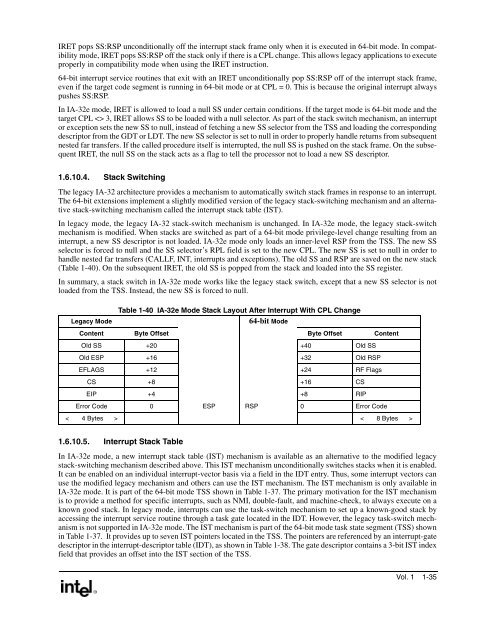
IRET pops SS:RSP unconditionally off the interrupt stack frame only when it is executed in <strong>64</strong>-bit mode. In compatibilitymode, IRET pops SS:RSP off the stack only if there is a CPL change. This allows legacy applications to executeproperly in compatibility mode when using the IRET instruction.<strong>64</strong>-bit interrupt service routines that exit with an IRET unconditionally pop SS:RSP off of the interrupt stack frame,even if the target code segment is running in <strong>64</strong>-bit mode or at CPL = 0. This is because the original interrupt alwayspushes SS:RSP.In IA-32e mode, IRET is allowed to load a null SS under certain conditions. If the target mode is <strong>64</strong>-bit mode and thetarget CPL 3, IRET allows SS to be loaded with a null selector. As part of the stack switch mechanism, an interruptor exception sets the new SS to null, instead of fetching a new SS selector from the TSS and loading the correspondingdescriptor from the GDT or LDT. The new SS selector is set to null in order to properly handle returns from subsequentnested far transfers. If the called procedure itself is interrupted, the null SS is pushed on the stack frame. On the subsequentIRET, the null SS on the stack acts as a flag to tell the processor not to load a new SS descriptor.1.6.10.4. Stack SwitchingThe legacy IA-32 architecture provides a mechanism to automatically switch stack frames in response to an interrupt.The <strong>64</strong>-bit extensions implement a slightly modified version of the legacy stack-switching mechanism and an alternativestack-switching mechanism called the interrupt stack table (IST).In legacy mode, the legacy IA-32 stack-switch mechanism is unchanged. In IA-32e mode, the legacy stack-switchmechanism is modified. When stacks are switched as part of a <strong>64</strong>-bit mode privilege-level change resulting from aninterrupt, a new SS descriptor is not loaded. IA-32e mode only loads an inner-level RSP from the TSS. The new SSselector is forced to null and the SS selector’s RPL field is set to the new CPL. The new SS is set to null in order tohandle nested far transfers (CALLF, INT, interrupts and exceptions). The old SS and RSP are saved on the new stack(Table 1-40). On the subsequent IRET, the old SS is popped from the stack and loaded into the SS register.In summary, a stack switch in IA-32e mode works like the legacy stack switch, except that a new SS selector is notloaded from the TSS. Instead, the new SS is forced to null.Table 1-40 IA-32e Mode Stack Layout After Interrupt With CPL ChangeLegacy Mode<strong>64</strong>-bit ModeContent Byte Offset Byte Offset ContentOld SS +20 +40 Old SSOld ESP +16 +32 Old RSPEFLAGS +12 +24 RF FlagsCS +8 +16 CSEIP +4 +8 RIPError Code 0 ESP RSP 0 Error Code< 4 Bytes > < 8 Bytes >1.6.10.5. Interrupt Stack TableIn IA-32e mode, a new interrupt stack table (IST) mechanism is available as an alternative to the modified legacystack-switching mechanism described above. This IST mechanism unconditionally switches stacks when it is enabled.It can be enabled on an individual interrupt-vector basis via a field in the IDT entry. Thus, some interrupt vectors canuse the modified legacy mechanism and others can use the IST mechanism. The IST mechanism is only available inIA-32e mode. It is part of the <strong>64</strong>-bit mode TSS shown in Table 1-37. The primary motivation for the IST mechanismis to provide a method for specific interrupts, such as NMI, double-fault, and machine-check, to always execute on aknown good stack. In legacy mode, interrupts can use the task-switch mechanism to set up a known-good stack byaccessing the interrupt service routine through a task gate located in the IDT. However, the legacy task-switch mechanismis not supported in IA-32e mode. The IST mechanism is part of the <strong>64</strong>-bit mode task state segment (TSS) shownin Table 1-37. It provides up to seven IST pointers located in the TSS. The pointers are referenced by an interrupt-gatedescriptor in the interrupt-descriptor table (IDT), as shown in Table 1-38. The gate descriptor contains a 3-bit IST indexfield that provides an offset into the IST section of the TSS.Vol. 1 1-35