- Page 1 and 2: Intel ® Extended Memory 64 Technol
- Page 4 and 5: 1.6.9.1. Call Gates. . . . . . . .
- Page 7 and 8: FSUB/FSUBP/FISUB—Subtract . . . .
- Page 9 and 10: PADDSB/PADDSW—Add Packed Signed I
- Page 12 and 13: -xii Vol. 1
- Page 14 and 15: ModeIA-32emodeOperatingSystemRequir
- Page 16 and 17: 1.3. REGISTER-SET CHANGESThis secti
- Page 18 and 19: Table 1-4 IA32_EFER Bit Description
- Page 20 and 21: IA-32e sub-modeTable 1-8 64-Bit Ext
- Page 22 and 23: REX PREFIX0100WR0BOpcodemod!=11ModR
- Page 24 and 25: 1.4.2.4. Direct Memory-Offset MOVsI
- Page 26 and 27: The 64-bit default operation-size e
- Page 28 and 29: 1.6.2. Register Settings and IA-32e
- Page 30 and 31: 1.6.3.4. Compatibility ModeCompatib
- Page 32 and 33: • When in compatibility mode, FS
- Page 34 and 35: Prior to activating IA-32e mode, PA
- Page 36 and 37: Table 1-22 through Table 1-24 shows
- Page 38 and 39: Table 1-26 Reserved Bit CheckingMod
- Page 40 and 41: • Bits 29:21 index into the 512-e
- Page 42 and 43: Only 64-bit mode call gates can be
- Page 44 and 45: Although the hardware task-switchin
- Page 46 and 47: Table 1-39 IA-32e Mode Interrupt an
- Page 48 and 49: If the IST index for an interrupt g
- Page 50 and 51: 1-38 Vol. 1
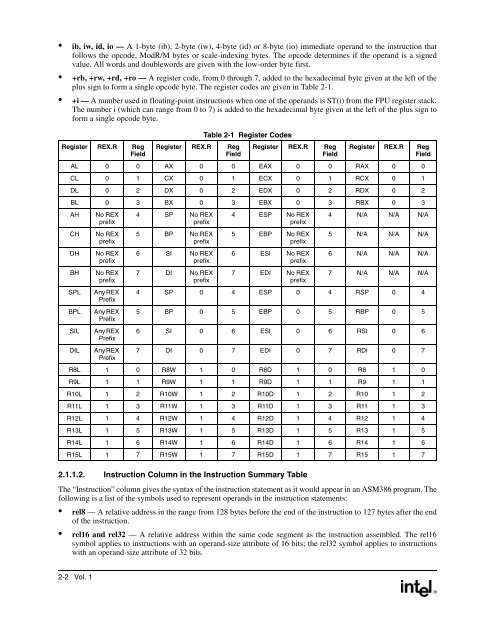
- Page 54 and 55: • m16:16, m16:32 & m16:64 —A me
- Page 56 and 57: which is either 16, 32 or 64-bits.
- Page 58 and 59: 2.1.3.1. IA-32e Mode OperationThe s
- Page 60 and 61: 2.1.10. SIMD Floating-Point Excepti
- Page 62 and 63: AAD—ASCII Adjust AX Before Divisi
- Page 64 and 65: AAS—ASCII Adjust AL After Subtrac
- Page 66 and 67: Real-Address Mode Exceptions#GPIf a
- Page 68 and 69: Real-Address Mode Exceptions#GPIf a
- Page 70 and 71: 64-Bit Mode Exceptions#SS(0)If a me
- Page 72 and 73: 64-Bit Mode Exceptions#SS(0)If a me
- Page 74 and 75: 64-Bit Mode Exceptions#SS(0)If a me
- Page 76 and 77: 64-Bit Mode Exceptions#SS(0)If a me
- Page 78 and 79: 64-Bit Mode Exceptions#SS(0)If a me
- Page 80 and 81: 64-Bit Mode Exceptions#SS(0)If a me
- Page 82 and 83: Real-Address Mode Exceptions#GPIf a
- Page 84 and 85: #PF(fault-code)#NM#UDFor a page fau
- Page 86 and 87: #PF(fault-code)#NM#UDFor a page fau
- Page 88 and 89: #PF(fault-code)#NM#UDFor a page fau
- Page 90 and 91: #PF(fault-code)#NM#UDFor a page fau
- Page 92 and 93: BOUND—Check Array Index Against B
- Page 94 and 95: BSF—Bit Scan ForwardOpcode Instru
- Page 96 and 97: BSWAP—Byte SwapOpcode Instruction
- Page 98 and 99: #AC(0)If alignment checking is enab
- Page 100 and 101: #GP(0)#PF(fault-code)#AC(0)If the m
- Page 102 and 103:
#PF(fault-code)#AC(0)If a page faul
- Page 104:
64-Bit Mode Exceptions#SS(0)If a me
- Page 107 and 108:
Compatibility Mode ExceptionsSame a
- Page 109 and 110:
CDQ—Convert Double to QuadSee ent
- Page 111 and 112:
CLD—Clear Direction FlagOpcode In
- Page 113 and 114:
CLI—Clear Interrupt FlagOpcode In
- Page 115 and 116:
CMC—Complement Carry FlagOpcode I
- Page 117 and 118:
Opcode Instruction 64-Bit Mode Comp
- Page 119 and 120:
CMP—Compare Two OperandsOpcode In
- Page 121 and 122:
CMPPD—Compare Packed Double-Preci
- Page 123 and 124:
CMPPS—Compare Packed Single-Preci
- Page 125 and 126:
CMPS/CMPSB/CMPSW/CMPSD/CMPSQ—Comp
- Page 127 and 128:
CMPSD—Compare Scalar Double-Preci
- Page 129 and 130:
CMPSS—Compare Scalar Single-Preci
- Page 131 and 132:
CMPXCHG—Compare and ExchangeOpcod
- Page 133 and 134:
CMPXCHG8B/CMPXCHG16B—Compare and
- Page 135 and 136:
COMISD—Compare Scalar Ordered Dou
- Page 137 and 138:
COMISS—Compare Scalar Ordered Sin
- Page 139 and 140:
CPUID—CPU IdentificationOpcode In
- Page 141 and 142:
Initial EAXValue80000005H80000006H8
- Page 143 and 144:
Table 2-8 CPUID Feature Information
- Page 145 and 146:
• The most significant bit (bit 3
- Page 147 and 148:
Table 2-10 Brand String Offsets (Co
- Page 149 and 150:
CVTDQ2PD—Convert Packed Doublewor
- Page 151 and 152:
CVTDQ2PS—Convert Packed Doublewor
- Page 153 and 154:
CVTPD2DQ—Convert Packed Double-Pr
- Page 155 and 156:
CVTPD2PI—Convert Packed Double-Pr
- Page 157 and 158:
CVTPD2PS—Covert Packed Double-Pre
- Page 159 and 160:
CVTPI2PD—Convert Packed Doublewor
- Page 161 and 162:
CVTPI2PS—Convert Packed Doublewor
- Page 163 and 164:
CVTPS2DQ—Convert Packed Single-Pr
- Page 165 and 166:
CVTPS2PD—Covert Packed Single-Pre
- Page 167 and 168:
CVTPS2PI—Convert Packed Single-Pr
- Page 169 and 170:
CVTSD2SI—Convert Scalar Double-Pr
- Page 171 and 172:
CVTSD2SS—Convert Scalar Double-Pr
- Page 173 and 174:
CVTSI2SD—Convert Doubleword Integ
- Page 175 and 176:
CVTSI2SS—Convert Doubleword Integ
- Page 177 and 178:
CVTSS2SD—Convert Scalar Single-Pr
- Page 179 and 180:
CVTSS2SI—Convert Scalar Single-Pr
- Page 181 and 182:
CVTTPD2PI—Convert with Truncation
- Page 183 and 184:
CVTTPD2DQ—Convert with Truncation
- Page 185 and 186:
CVTTPS2DQ—Convert with Truncation
- Page 187 and 188:
CVTTPS2PI—Convert with Truncation
- Page 189 and 190:
CVTTSD2SI—Convert with Truncation
- Page 191 and 192:
CVTTSS2SI—Convert with Truncation
- Page 193 and 194:
CWD/CDQ/CQQ—Convert Word to Doubl
- Page 195 and 196:
DAS—Decimal Adjust AL after Subtr
- Page 197 and 198:
64-Bit Mode Exceptions#SS(0)If a me
- Page 199 and 200:
Virtual-8086 Mode Exceptions#DE If
- Page 201 and 202:
64-Bit Mode Exceptions#SS(0)If a me
- Page 203 and 204:
64-Bit Mode Exceptions#SS(0)If a me
- Page 205 and 206:
64-Bit Mode Exceptions#SS(0)If a me
- Page 207 and 208:
64-Bit Mode Exceptions#SS(0)If a me
- Page 209 and 210:
ENTER—Make Stack Frame for Proced
- Page 211 and 212:
FABS—Absolute ValueOpcode Instruc
- Page 213 and 214:
Real-Address Mode Exceptions#GPIf a
- Page 215 and 216:
64-Bit Mode Exceptions#SS(0)If a me
- Page 217 and 218:
Virtual-8086 Mode Exceptions#GP(0)I
- Page 219 and 220:
FCLEX/FNCLEX—Clear ExceptionsOpco
- Page 221 and 222:
FCOM/FCOMP/FCOMPP—Compare Floatin
- Page 223 and 224:
FCOMI/FCOMIP/ FUCOMI/FUCOMIP—Comp
- Page 225 and 226:
FDECSTP—Decrement Stack-Top Point
- Page 227 and 228:
Real-Address Mode Exceptions#GPIf a
- Page 229 and 230:
Real-Address Mode Exceptions#GPIf a
- Page 231 and 232:
FICOM/FICOMP—Compare IntegerOpcod
- Page 233 and 234:
FILD—Load IntegerOpcode Instructi
- Page 235 and 236:
FINCSTP—Increment Stack-Top Point
- Page 237 and 238:
FIST/FISTP—Store IntegerOpcode In
- Page 239 and 240:
FISTTP—Store Integer with Truncat
- Page 241 and 242:
FLD—Load Floating Point ValueOpco
- Page 243 and 244:
FLD1/FLDL2T/FLDL2E/FLDPI/FLDLG2/FLD
- Page 245 and 246:
64-Bit Mode Exceptions#SS(0)If a me
- Page 247 and 248:
Compatibility Mode ExceptionsSame a
- Page 249 and 250:
Real-Address Mode Exceptions#GPIf a
- Page 251 and 252:
FPATAN—Partial ArctangentOpcode I
- Page 253 and 254:
FPREM1—Partial RemainderOpcode In
- Page 255 and 256:
FRNDINT—Round to IntegerOpcode In
- Page 257 and 258:
64-Bit Mode Exceptions#SS(0)If a me
- Page 259 and 260:
Virtual-8086 Mode Exceptions#GP(0)I
- Page 261 and 262:
FSIN—SineOpcode Instruction 64-Bi
- Page 263 and 264:
FSQRT—Square RootOpcode Instructi
- Page 265 and 266:
Real-Address Mode Exceptions#GPIf a
- Page 267 and 268:
Virtual-8086 Mode Exceptions#GP(0)I
- Page 269 and 270:
Virtual-8086 Mode Exceptions#GP(0)I
- Page 271 and 272:
Virtual-8086 Mode Exceptions#GP(0)I
- Page 273 and 274:
Protected Mode Exceptions#GP(0)If a
- Page 275 and 276:
Protected Mode Exceptions#GP(0)If a
- Page 277 and 278:
FUCOM/FUCOMP/FUCOMPP—Unordered Co
- Page 279 and 280:
FXAM—ExamineOpcode Instruction 64
- Page 281 and 282:
FXRSTOR—Restore x87 FPU, MMX, SSE
- Page 283 and 284:
FXSAVE—Save x87 FPU, MMX, SSE, an
- Page 285 and 286:
XMM0 throughXMM7XMM registers (128
- Page 287 and 288:
Table 2-14 Layout of the 64-bit FXS
- Page 289 and 290:
Protected Mode Exceptions#GP(0)For
- Page 291 and 292:
FXTRACT—Extract Exponent and Sign
- Page 293 and 294:
FYL2XP1—Compute y ∗ log 2 (x +1
- Page 295 and 296:
64-Bit Mode Exceptions#SS(0)If a me
- Page 297 and 298:
64-Bit Mode Exceptions#SS(0)If a me
- Page 299 and 300:
HSUBPD—Horizontal Subtract Packed
- Page 301 and 302:
HSUBPS—Horizontal Subtract Packed
- Page 303 and 304:
IDIV—Signed DivideOpcode Instruct
- Page 305 and 306:
IMUL—Signed MultiplyOpcode Instru
- Page 307 and 308:
IN—Input from PortOpcode Instruct
- Page 309 and 310:
64-Bit Mode Exceptions#SS(0)If a me
- Page 311 and 312:
Compatibility Mode ExceptionsSame a
- Page 313 and 314:
Real-Address Mode Exceptions#GPIf a
- Page 315 and 316:
INVD—Invalidate Internal CachesOp
- Page 317 and 318:
IRET/IRETD—Interrupt ReturnOpcode
- Page 319 and 320:
Jcc—Jump if Condition Is MetOpcod
- Page 321 and 322:
Opcode Instruction 64-Bit Mode Comp
- Page 323 and 324:
#SS(0)#NP (selector)#PF(fault-code)
- Page 325 and 326:
LAHF—Load Status Flags into AH Re
- Page 327 and 328:
LDDQU—Load Unaligned Double Quadw
- Page 329 and 330:
LDMXCSR—Load MXCSR RegisterOpcode
- Page 331 and 332:
LDS/LES/LFS/LGS/LSS—Load Far Poin
- Page 333 and 334:
LEA—Load Effective AddressOpcode
- Page 335 and 336:
LES—Load Full PointerSee entry fo
- Page 337 and 338:
LFS—Load Full PointerSee entry fo
- Page 339 and 340:
LGS—Load Full PointerSee entry fo
- Page 341 and 342:
64-Bit Mode Exceptions#SS(0)If a me
- Page 343 and 344:
LMSW—Load Machine Status WordOpco
- Page 345 and 346:
LODS/LODSB/LODSW/LODSD/LODSQ—Load
- Page 347 and 348:
LOOP/LOOPcc—Loop According to ECX
- Page 349 and 350:
LSS—Load Full PointerSee entry fo
- Page 351 and 352:
64-Bit Mode Exceptions#SS(0)If a me