- Page 1:
REPAIR MANUALSELF-PROPELLED TELESCO
- Page 4 and 5:
21 Repair manual
- Page 6 and 7:
Repair Manual2.2.1 - H14T(X) size .
- Page 8 and 9:
Repair Manual5.18.4 - Indicator def
- Page 10 and 11:
6Repair Manual
- Page 12 and 13:
Repair manual1.2 - GENERAL SAFETY I
- Page 14 and 15:
Repair manual1.3 - RESIDUAL RISKSCa
- Page 16 and 17:
1.5 - REPAIRS AND ADJUSTMENTS1.6 -
- Page 18 and 19:
Repair manualDESCRIPTION H14T(X) Un
- Page 20 and 21:
Repair manual2.2 - SIZE2.2.1 - H14T
- Page 22 and 23:
Repair manual2.3 - TIGHTENING TORQU
- Page 24 and 25:
20Repair manual
- Page 26 and 27:
Repair manual3.1.4 - Safety inputsS
- Page 28 and 29:
24Repair manual
- Page 30 and 31:
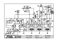
Repair manual4.2 - DIAGRAM E 523 -
- Page 32 and 33:
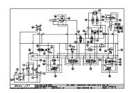
Repair manual4.4 - DIAGRAM E 523 -
- Page 34 and 35:
30Repair manual
- Page 36 and 37:
135 Repair manual5.6 - JIB5.6.1 - U
- Page 38 and 39:
135 Repair manual5.10.2 -Platform5.
- Page 40 and 41:
135 Repair manual5.18 - OTHER FUNCT
- Page 42 and 43:
135 Repair manual6.1.2 - Positions
- Page 44 and 45:
135 Repair manual6.1.4 - Positions
- Page 46 and 47:
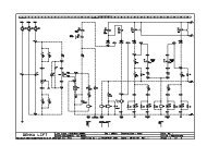
Repair manual7.2 - DIAGRAM H16TP(X)
- Page 48 and 49:
Repair manualTo preserve the integr
- Page 50 and 51:
Repair manual8.5 - MAINTENANCE PLAN
- Page 52 and 53:
Repair manual8.6 - OPERATIONS8.6.1
- Page 54 and 55:
Repair manualRef Code Qty Descripti
- Page 56 and 57:
Repair manual8.7.3 - Common "yellow
- Page 58 and 59:
Repair manual8.7.5 - Labels specifi
- Page 60 and 61:
Repair manual24 2356
- Page 62 and 63:
58Repair manual
- Page 64 and 65:
60135 Repair manual
- Page 67 and 68:
PREVENTIVE MAINTENANCE SHEETSheet P
- Page 69 and 70:
PREVENTIVE MAINTENANCE SHEETSheet P
- Page 71 and 72:
Repair manual10 - OPERATING INCIDEN
- Page 73 and 74:
Repair manualNo movement available
- Page 75 and 76:
Repair manual10.1.3 -Travel systemA
- Page 77 and 78:
Sheet DP015BREAKDOWN DETECTION FLOW
- Page 79 and 80:
Sheet DP016BREAKDOWN DETECTION FLOW
- Page 81:
Sheet DP016BREAKDOWN DETECTION FLOW
- Page 84 and 85:
Sheet DP018BREAKDOWN DETECTION FLOW
- Page 87 and 88:
Sheet DP019BREAKDOWN DETECTION FLOW
- Page 89:
Sheet DP020BREAKDOWN DETECTION FLOW
- Page 93 and 94:
Sheet DP022BREAKDOWN DETECTION FLOW
- Page 95 and 96:
Sheet DP023BREAKDOWN DETECTION FLOW
- Page 97 and 98:
Sheet DP023BREAKDOWN DETECTION FLOW
- Page 99:
Sheet DP023BREAKDOWN DETECTION FLOW
- Page 102 and 103:
Sheet DP024BREAKDOWN DETECTION FLOW
- Page 104 and 105:
Sheet DP025BREAKDOWN DETECTION FLOW
- Page 106 and 107:
Sheet DP026BREAKDOWN DETECTION FLOW
- Page 108 and 109:
Sheet DP026BREAKDOWN DETECTION FLOW
- Page 111 and 112:
Sheet DP027BREAKDOWN DETECTION FLOW
- Page 113 and 114:
Sheet DP027BREAKDOWN DETECTION FLOW
- Page 115:
Sheet DP027BREAKDOWN DETECTION FLOW
- Page 118 and 119:
Sheet DP028BREAKDOWN DETECTION FLOW
- Page 120 and 121:
Sheet DP028BREAKDOWN DETECTION FLOW
- Page 123 and 124:
Sheet DP030BREAKDOWN DETECTION FLOW
- Page 125:
Sheet DP030BREAKDOWN DETECTION FLOW
- Page 128 and 129:
Sheet DP032BREAKDOWN DETECTION FLOW
- Page 130 and 131:
Sheet DP032BREAKDOWN DETECTION FLOW
- Page 132 and 133:
Sheet DP034BREAKDOWN DETECTION FLOW
- Page 134 and 135:
Sheet DP034BREAKDOWN DETECTION FLOW
- Page 136 and 137:
Sheet DP036BREAKDOWN DETECTION FLOW
- Page 139:
Sheet DP041BREAKDOWN DETECTION FLOW
- Page 142 and 143:
Sheet DP056BREAKDOWN DETECTION FLOW
- Page 145 and 146:
Sheet DP060BREAKDOWN DETECTION FLOW
- Page 147 and 148:
Sheet DP060BREAKDOWN DETECTION FLOW
- Page 149 and 150:
Sheet DP072BREAKDOWN DETECTION FLOW
- Page 151 and 152:
Sheet DP072BREAKDOWN DETECTION FLOW
- Page 153 and 154:
Repair manual11 - CORRECTIVE MAINTE
- Page 155:
Sheet C010CORRECTIVE MAINTENANCE SH
- Page 159 and 160:
Sheet C035CORRECTIVE MAINTENANCE SH
- Page 161: Sheet C038CORRECTIVE MAINTENANCE SH
- Page 165: CORRECTIVE MAINTENANCE SHEETSheet C
- Page 169 and 170: Sheet C042CORRECTIVE MAINTENANCE SH
- Page 171: Sheet C043CORRECTIVE MAINTENANCE SH
- Page 175: Sheet C045CORRECTIVE MAINTENANCE SH
- Page 179: CORRECTIVE MAINTENANCE SHEETSheet C
- Page 183: Sheet C051CORRECTIVE MAINTENANCE SH
- Page 187 and 188: CORRECTIVE MAINTENANCE SHEETSheet C
- Page 189: Sheet C053CORRECTIVE MAINTENANCE SH
- Page 193 and 194: Sheet C055CORRECTIVE MAINTENANCE SH
- Page 195 and 196: CORRECTIVE MAINTENANCE SHEETSheet C
- Page 197: Sheet C058CORRECTIVE MAINTENANCE SH
- Page 201 and 202: Sheet C062CORRECTIVE MAINTENANCE SH
- Page 203: Sheet C063CORRECTIVE MAINTENANCE SH
- Page 207 and 208: CORRECTIVE MAINTENANCE SHEETSheet C
- Page 209: Sheet C067CORRECTIVE MAINTENANCE SH
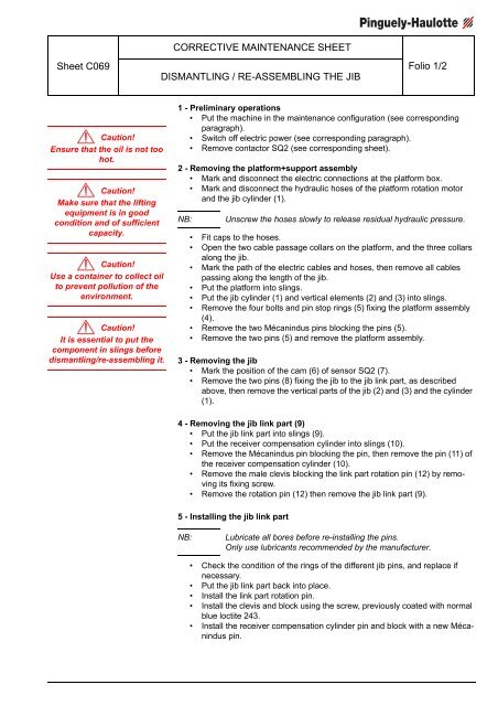
- Page 214 and 215: Sheet C069CORRECTIVE MAINTENANCE SH
- Page 216 and 217: Sheet C073CORRECTIVE MAINTENANCE SH
- Page 218 and 219: Sheet C073CORRECTIVE MAINTENANCE SH
- Page 220 and 221: Sheet C074CORRECTIVE MAINTENANCE SH
- Page 222 and 223: Sheet C075CORRECTIVE MAINTENANCE SH
- Page 225 and 226: CORRECTIVE MAINTENANCE SHEETSheet C
- Page 227: Sheet C079CORRECTIVE MAINTENANCE SH
- Page 231: Sheet C082CORRECTIVE MAINTENANCE SH
- Page 235 and 236: Sheet C120CORRECTIVE MAINTENANCE SH
- Page 237 and 238: Sheet C121CORRECTIVE MAINTENANCE SH
- Page 239 and 240: Sheet C121CORRECTIVE MAINTENANCE SH
- Page 241 and 242: CORRECTIVE MAINTENANCE SHEETSheet C
- Page 243: CORRECTIVE MAINTENANCE SHEETSheet C
- Page 247: CORRECTIVE MAINTENANCE SHEETSheet C
- Page 250 and 251: Sheet C126CORRECTIVE MAINTENANCE SH
- Page 253 and 254: Sheet C128CORRECTIVE MAINTENANCE SH
- Page 255 and 256: Sheet C128CORRECTIVE MAINTENANCE SH
- Page 257 and 258: Sheet C128CORRECTIVE MAINTENANCE SH
- Page 259 and 260: Sheet C129CORRECTIVE MAINTENANCE SH
- Page 261 and 262: Sheet C129CORRECTIVE MAINTENANCE SH
- Page 263 and 264:
Sheet C129CORRECTIVE MAINTENANCE SH
- Page 265 and 266:
Sheet C130CORRECTIVE MAINTENANCE SH
- Page 267 and 268:
Sheet C131CORRECTIVE MAINTENANCE SH
- Page 269 and 270:
Sheet C136CORRECTIVE MAINTENANCE SH
- Page 271 and 272:
Sheet C138CORRECTIVE MAINTENANCE SH