h16tp(x - AJ Maskin AS
h16tp(x - AJ Maskin AS
h16tp(x - AJ Maskin AS
- No tags were found...

You also want an ePaper? Increase the reach of your titles
YUMPU automatically turns print PDFs into web optimized ePapers that Google loves.
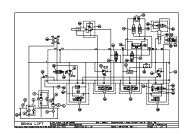
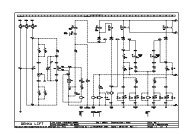
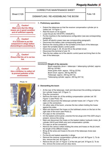
Sheet C129CORRECTIVE MAINTENANCE SHEETDISMANTLING / RE-<strong>AS</strong>SEMBLING THE BOOMFolio 1/6Caution!Make sure that the liftingmeans are in good conditionand of sufficient capacity.Caution!It is essential to put thecomponent in slings beforedismantling/re-assembling it.Caution!Ensure that the oil is not toohot.Caution!Use a container to collect oilto prevent pollution of theenvironment.1 - Preliminary operations• Extend the telescope so that the receiver compensation cylinder pin isvisible (ref. 10 Figure 1).• Rest the boom on its support.• Lower the jib (for HA16TPX, HA46JRT)).• Put the machine in the maintenance configuration (see see correspondingparagraph).• Switch off electric power (see see corresponding paragraph).• Disconnect the battery (see corresponding sheet).• Remove the closing plate on the turntable at the back of the telescope.• Open the turntable electric control panel.• Disconnect plugs 3, 29, 30 and 49 on the printed circuit.• Disconnect the terminal of wire 16.• Take the two cables out of the electric control panel and bring them to therear of the telescope.REMINDER:Weight of the elements:Boom assembly (drum + telescope + telescoping cylinder): approx.850 kg (1874lb)Hose guide chain: approx. 100 kg (221lb)Boom drum: approx. 300 kg (662 lb)Telescope: approx. 200 kg (441 lb)Telescoping cylinder: approx. 200 kg (441 lb)Photo 142 - Dismantling the boom• At the rear of the telescope, mark and disconnect the emitting compensationcylinder hoses (ref. 2 Figure 1).• Plug the connectors.• Remove the lower pin of the emitting compensation cylinder (ref. 50Figure 1) (see Photo 14).• Mark and disconnect the telescope cylinder hoses (ref. 3 Figure 1) Putcaps on the connectors.• On either side of the boom, unscrew the two collars holding the hosesagainst the sides.• Mark and disconnect the hoses on the bulkhead unions on the bar on theright side of the boom (see Photo 2).• Put caps on the connectors.• On the basket control panel, unscrew the two plugs and if the 220V plug ispresent, remove the wiring.• Mark and disconnect the hoses on the basket rotation hydraulic motor, jibcylinder (HA16 and HA46 only) and compensation cylinder.• Put caps on all the connectors.• Remove the various collars holding the wires and hoses on the jib (markthe length of the different loops).• Bring all the wires and hoses to the end of the telescope chute (seePhoto 3).• Put the jib and basket assembly in slings.• Remove the receiver compensation cylinder pin (ref. 48 Figure 1). To dothis, remove the (ref. 49 Figure 1).• Remove the pin (ref. 47 Figure 1) of the link part (ref. 8 Figure 2). To dothis, remove the screw and pin stop clevis.