Single-Chip Low Cost Low Power RF-Transceiver (Rev. A)
Single-Chip Low Cost Low Power RF-Transceiver (Rev. A)
Single-Chip Low Cost Low Power RF-Transceiver (Rev. A)

Create successful ePaper yourself
Turn your PDF publications into a flip-book with our unique Google optimized e-Paper software.
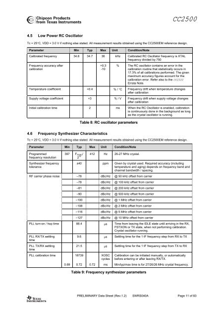
CC25004.5 <strong>Low</strong> <strong>Power</strong> RC OscillatorTc = 25°C, VDD = 3.0 V if nothing else stated. All measurement results obtained using the CC2500EM reference design.Parameter Min Typ Max Unit Condition/NoteCalibrated frequency 34.6 34.7 36 kHz Calibrated RC Oscillator frequency is XTALfrequency divided by 750Frequency accuracy aftercalibration+0.3-10% The RC oscillator contains an error in thecalibration routine that statistically occurs in17.3% of all calibrations performed. The givenmaximum accuracy figures account for thecalibration error. Refer also to the CC2500Errata Note.Temperature coefficient +0.4 % / °C Frequency drift when temperature changesafter calibrationSupply voltage coefficient +3 % / V Frequency drift when supply voltage changesafter calibrationInitial calibration time 2 ms When the RC Oscillator is enabled, calibrationis continuously done in the background as longas the crystal oscillator is running.Table 8: RC oscillator parameters4.6 Frequency Synthesizer CharacteristicsTc = 25°C, VDD = 3.0 V if nothing else stated. All measurement results obtained using the CC2500EM reference design.Parameter Min Typ Max Unit Condition/NoteProgrammedfrequency resolutionSynthesizer frequencytolerance<strong>RF</strong> carrier phase noise397 F XOSC /2 16 412 Hz 26-27 MHz crystal.±40 ppm Given by crystal used. Required accuracy (includingtemperature and aging) depends on frequency band andchannel bandwidth / spacing.–78 dBc/Hz @ 50 kHz offset from carrier–78 dBc/Hz @ 100 kHz offset from carrier–81 dBc/Hz @ 200 kHz offset from carrier–90 dBc/Hz @ 500 kHz offset from carrier–100 dBc/Hz @ 1 MHz offset from carrier–108 dBc/Hz @ 2 MHz offset from carrier–116 dBc/Hz @ 5 MHz offset from carrier–127 dBc/Hz @ 10 MHz offset from carrierPLL turn-on / hop time 88.4 µs Time from leaving the IDLE state until arriving in the RX,FSTXON or TX state, when not performing calibration.Crystal oscillator running.PLL RX/TX settlingtimePLL TX/RX settlingtimePLL calibration time0.699.6 µs Settling time for the 1·IF frequency step from RX to TX21.5 µs Settling time for the 1·IF frequency step from TX to RX187390.72 0.72XOSCcyclesmsTable 9: Frequency synthesizer parametersCalibration can be initiated manually, or automaticallybefore entering or after leaving RX/TX.Min/typ/max time is for 27/26/26 MHz crystal frequency.PRELIMINARY Data Sheet (<strong>Rev</strong>.1.2) SWRS040A Page 11 of 83

![td-res-4 [Compatibility Mode]](https://img.yumpu.com/45826987/1/184x260/td-res-4-compatibility-mode.jpg?quality=85)