Single-Chip Low Cost Low Power RF-Transceiver (Rev. A)
Single-Chip Low Cost Low Power RF-Transceiver (Rev. A)
Single-Chip Low Cost Low Power RF-Transceiver (Rev. A)

Create successful ePaper yourself
Turn your PDF publications into a flip-book with our unique Google optimized e-Paper software.
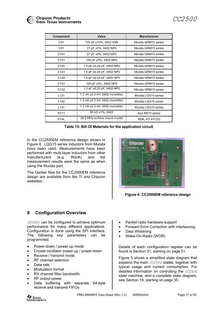
CC2500Component Value ManufacturerC51 100 nF ±10%, 0402 X5R Murata GRM15 seriesC81 27 pF ±5%, 0402 NP0 Murata GRM15 seriesC101 27 pF ±5%, 0402 NP0 Murata GRM15 seriesC121 100 pF ±5%, 0402 NP0 Murata GRM15 seriesC122 1.0 pF ±0.25 pF, 0402 NP0 Murata GRM15 seriesC123 1.8 pF ±0.25 pF, 0402 NP0 Murata GRM15 seriesC124 1.5 pF ±0.25 pF, 0402 NP0 Murata GRM15 seriesC131 100 pF ±5%, 0402 NP0 Murata GRM15 seriesC132 1.0 pF ±0.25 pF, 0402 NP0 Murata GRM15 seriesL121 1.2 nH ±0.3 nH, 0402 monolithic Murata LQG15 seriesL122 1.2 nH ±0.3 nH, 0402 monolithic Murata LQG15 seriesL131 1.2 nH ±0.3 nH, 0402 monolithic Murata LQG15 seriesR171 56 kΩ ±1%, 0402 Koa RK73 seriesXTAL 26.0 MHz surface mount crystal NDK, AT-41CD2Table 15: Bill Of Materials for the application circuitIn the CC2500EM reference design shown inFigure 4, LQG15 series inductors from Muratahave been used. Measurements have beenperformed with multi-layer inductors from othermanufacturers (e.g. Würth) and themeasurement results were the same as whenusing the Murata part.The Gerber files for the CC2500EM referencedesign are available from the TI and <strong>Chip</strong>conwebsites.Figure 4: CC2500EM reference design8 Configuration OverviewCC2500 can be configured to achieve optimumperformance for many different applications.Configuration is done using the SPI interface.The following key parameters can beprogrammed:• <strong>Power</strong>-down / power up mode• Crystal oscillator power-up / power-down• Receive / transmit mode• <strong>RF</strong> channel selection• Data rate• Modulation format• RX channel filter bandwidth• <strong>RF</strong> output power• Data buffering with separate 64-bytereceive and transmit FIFOs• Packet radio hardware support• Forward Error Correction with interleaving• Data Whitening• Wake-On-Radio (WOR)Details of each configuration register can befound in Section 31, starting on page 51.Figure 5 shows a simplified state diagram thatexplains the main CC2500 states, together withtypical usage and current consumption. Fordetailed information on controlling the CC2500state machine, and a complete state diagram,see Section 19, starting on page 35.PRELIMINARY Data Sheet (<strong>Rev</strong>.1.2) SWRS040A Page 17 of 83


![td-res-4 [Compatibility Mode]](https://img.yumpu.com/45826987/1/184x260/td-res-4-compatibility-mode.jpg?quality=85)