Single-Chip Low Cost Low Power RF-Transceiver (Rev. A)
Single-Chip Low Cost Low Power RF-Transceiver (Rev. A)
Single-Chip Low Cost Low Power RF-Transceiver (Rev. A)

Create successful ePaper yourself
Turn your PDF publications into a flip-book with our unique Google optimized e-Paper software.
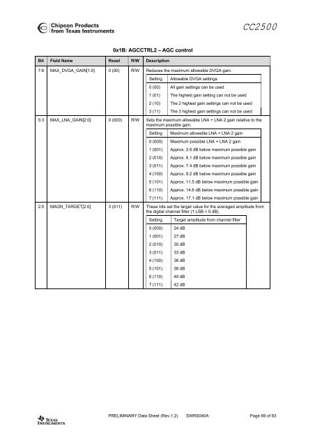
CC25000x1B: AGCCTRL2 – AGC controlBit Field Name Reset R/W Description7:6 MAX_DVGA_GAIN[1:0] 0 (00) R/W Reduces the maximum allowable DVGA gain.SettingAllowable DVGA settings0 (00) All gain settings can be used1 (01) The highest gain setting can not be used2 (10) The 2 highest gain settings can not be used3 (11) The 3 highest gain settings can not be used5:3 MAX_LNA_GAIN[2:0] 0 (000) R/W Sets the maximum allowable LNA + LNA 2 gain relative to themaximum possible gain.SettingMaximum allowable LNA + LNA 2 gain0 (000) Maximum possible LNA + LNA 2 gain1 (001) Approx. 2.6 dB below maximum possible gain2 (010) Approx. 6.1 dB below maximum possible gain3 (011) Approx. 7.4 dB below maximum possible gain4 (100) Approx. 9.2 dB below maximum possible gain5 (101) Approx. 11.5 dB below maximum possible gain6 (110) Approx. 14.6 dB below maximum possible gain7 (111) Approx. 17.1 dB below maximum possible gain2:0 MAGN_TARGET[2:0] 3 (011) R/W These bits set the target value for the averaged amplitude fromthe digital channel filter (1 LSB = 0 dB).Setting0 (000) 24 dB1 (001) 27 dB2 (010) 30 dB3 (011) 33 dB4 (100) 36 dB5 (101) 38 dB6 (110) 40 dB7 (111) 42 dBTarget amplitude from channel filterPRELIMINARY Data Sheet (<strong>Rev</strong>.1.2) SWRS040A Page 69 of 83

![td-res-4 [Compatibility Mode]](https://img.yumpu.com/45826987/1/184x260/td-res-4-compatibility-mode.jpg?quality=85)