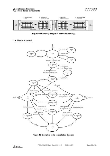
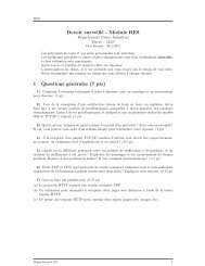
CC2500otherwise remain in RX. This feature is calledTX if CCA.Four CCA requirements can be programmed:• Always (CCA disabled, always goes to TX)• If RSSI is below threshold• Unless currently receiving a packet• Both the above (RSSI below threshold andnot currently receiving a packet)17.6 Link Quality Indicator (LQI)The Link Quality Indicator is a metric of thecurrent quality of the received signal. IfPKTCTRL1.APPEND_STATUS is enabled, thevalue is automatically appended to the end ofeach received packet. The value can also beread from the LQI status register. The LQI iscalculated over the 64 symbols following thesync word (first 8 packet bytes). LQI is bestused as a relative measurement of the linkquality, since the value is dependent on themodulation format.18 Forward Error Correction with Interleaving18.1 Forward Error Correction (FEC)CC2500 has built in support for Forward ErrorCorrection (FEC). To enable this option, setMDMCFG1.FEC_EN to 1. FEC is only supportedin fixed packet length mode(PKTCTRL0.LENGTH_CONFIG=0). FEC isemployed on the data field and CRC word inorder to reduce the gross bit error rate whenoperating near the sensitivity limit.Redundancy is added to the transmitted datain such a way that the receiver can restore theoriginal data in the presence of some biterrors.The use of FEC allows correct reception at alower SNR, thus extending communicationrange. Alternatively, for a given SNR, usingFEC decreases the bit error rate (BER). As thepacket error rate (PER) is related to BER by:PER = 1−(1 − BER)packet _ lengtha lower BER can be used to allow longerpackets, or a higher percentage of packets ofa given length, to be transmitted successfully.Finally, in realistic ISM radio environments,transient and time-varying phenomena willproduce occasional errors even in otherwisegood reception conditions. FEC will mask sucherrors and, combined with interleaving of thecoded data, even correct relatively longperiods of faulty reception (burst errors).The FEC scheme adopted for CC2500 isconvolutional coding, in which n bits aregenerated based on k input bits and the mmost recent input bits, forming a code streamable to withstand a certain number of bit errorsbetween each coding state (the m-bit window).The convolutional coder is a rate 1/2 code witha constraint length of m=4. The coder codesone input bit and produces two output bits;hence, the effective data rate is halved.18.2 InterleavingData received through radio channels willoften experience burst errors due tointerference and time-varying signal strengths.In order to increase the robustness to errorsspanning multiple bits, interleaving is usedwhen FEC is enabled. After de-interleaving, acontinuous span of errors in the receivedstream will become single errors spread apart.CC2500 employs matrix interleaving, which isillustrated in Figure 14. The on-chipinterleaving and de-interleaving buffers are 4 x4 matrices. In the transmitter, the data bits arewritten into the rows of the matrix, whereas thebit sequence to be transmitted is read from thecolumns of the matrix and fed to the rate ½convolutional coder. Conversely, in thereceiver, the received symbols are written intothe columns of the matrix, whereas the datapassed onto the convolutional decoder is readfrom the rows of the matrix.When FEC and interleaving is used at leastone extra byte is required for trellistermination. In addition, the amount of datatransmitted over the air must be a multiple ofthe size of the interleaver buffer (two bytes).The packet control hardware thereforeautomatically inserts one or two extra bytes atthe end of the packet, so that the total lengthof the data to be interleaved is an evennumber. Note that these extra bytes areinvisible to the user, as they are removedbefore the received packet enters the RXFIFO.When FEC and interleaving is used theminimum data payload is 2 bytes.PRELIMINARY Data Sheet (<strong>Rev</strong>.1.2) SWRS040A Page 34 of 83
CC25001) Storing codeddata2) Transmittinginterleaved data3) Receivinginterleaved data4) Passing on datato decoderTXDataEncoderTransmitterModulatorDemodulatorReceiverDecoderRXDataFigure 14: General principle of matrix interleaving19 Radio ControlSIDLECAL_ COMPLETESPWD | SWORSLEEP0MANCAL3,4,5SCALIDLE1CSn = 0 | WORSXOFFSRX | STX | SFSTXON | WORCSn = 0XOFF2FS_ WAKEUP6,7FS_ AUTOCAL = 01&SRX | STX | SFSTXON | WO<strong>RF</strong>S_ AUTOCAL = 00 | 10 | 11&SRX | STX | SFSTXON | WORCALIBRATE8SFSTXONSETTLING9,10,11CAL_ COMPLETEFSTXON18STXSRX | WORSTXTXOFF_ MODE=01SFSTXON | RXOFF_ MODE = 01SRXSTX | RXOFF_ MODE = 10RXTX_ SETTLING( STX | SFSTXON ) & CCA21|TXOFF_ MODE = 10TXRXOFF_ MODE = 01 | 10RX19,2013,14,15RXOFF_ MODE = 11SRX | TXOFF_ MODE = 11TXRX_ SETTLING16TXFIFO_ UNDE<strong>RF</strong>LOWTXOFF_ MODE = 00&FS_ AUTOCAL = 10 | 11RXOFF_ MODE = 00&FS_ AUTOCAL = 10 | 11RXFIFO_ OVE<strong>RF</strong>LOWTX_ UNDE<strong>RF</strong>LOW22TXOFF_ MODE = 00&FS_ AUTOCAL = 00 | 01CALIBRATE12RXOFF_ MODE = 00&FS_ AUTOCAL = 00 | 01RX_ OVE<strong>RF</strong>LOW17SFTXSFRXIDLE1Figure 15: Complete radio control state diagramPRELIMINARY Data Sheet (<strong>Rev</strong>.1.2) SWRS040A Page 35 of 83


![td-res-4 [Compatibility Mode]](https://img.yumpu.com/45826987/1/184x260/td-res-4-compatibility-mode.jpg?quality=85)