Single-Chip Low Cost Low Power RF-Transceiver (Rev. A)
Single-Chip Low Cost Low Power RF-Transceiver (Rev. A)
Single-Chip Low Cost Low Power RF-Transceiver (Rev. A)

You also want an ePaper? Increase the reach of your titles
YUMPU automatically turns print PDFs into web optimized ePapers that Google loves.
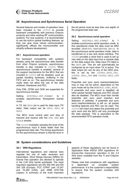
CC250029 Asynchronous and Synchronous Serial OperationSeveral features and modes of operation havebeen included in the CC2500 to providebackward compatibility with previous <strong>Chip</strong>conproducts and other existing <strong>RF</strong> communicationsystems. For new systems, it is recommendedto use the built-in packet handling features, asthey can give more robust communication,significantly offload the microcontroller andsimplify software development.29.1 Asynchronous operationFor backward compatibility with systemsalready using the asynchronous data transferfrom other <strong>Chip</strong>con products, asynchronoustransfer is also included in CC2500. Whenasynchronous transfer is enabled, several ofthe support mechanisms for the MCU that areincluded in CC2500 will be disabled, such aspacket handling hardware, buffering in theFIFO and so on. The asynchronous transfermode does not allow the use of the datawhitener, interleaver and FEC.Only FSK, GFSK and OOK are supported forasynchronous transfer.Setting PKTCTRL0.PKT_FORMAT to 3enables asynchronous transparent (serial)mode.In TX, the GDO0 pin is used for data input (TXdata). Data output can be GDO0, GDO1 orGDO2.The MCU must control start and stop oftransmit and receive with the STX, SRX andSIDLE strobes.The CC2500 modulator samples the level of theasynchronous input 8 times faster than theprogrammed data rate. The timing requirementfor the asynchronous stream is that the error inthe bit period must be less than one eighth ofthe programmed data rate.29.2 Synchronous serial operationSetting PKTCTRL0.PKT_FORMAT to 1enables synchronous serial operation mode. Inthis operational mode the data must be NRZencoded (MDMCFG2.MANCHESTER_EN=0). Inthe synchronous serial operation mode, data istransferred on a two wire serial interface. TheCC2500 provides a clock that is used to set upnew data on the data input line or sample dataon the data output line. Data input (TX data) isthe GDO0 pin. This pin will automatically beconfigured as an input when TX is active. Thedata output pin can be any of the GDO pins;this is set by the IOCFG0.GDO0_CFG,IOCFG1.GDO1_CFG and IOCFG2.GDO2_CFGfields.Preamble and sync word insertion/detectionmay or may not be active, dependent on thesync mode set by the MDMCFG2.SYNC_MODE.If preamble and sync word is disabled, allother packet handler features and FEC shouldalso be disabled. The MCU must then handlepreamble and sync word insertion anddetection in software. If preamble and syncword insertion/detection is left on, all packethandling features and FEC can be used. TheCC2500 will insert and detect the preamble andsync word and the MCU will only provide/getthe data payload. This is equivalent to therecommended FIFO operation mode.30 System considerations and Guidelines30.1 SRD RegulationsInternational regulations and national lawsregulate the use of radio receivers andtransmitters. Short Range Devices (SRDs) forlicense free operation are allowed to operatein the 2.45 GHz bands worldwide. The mostimportant regulations are EN 300 440 and EN300 328 (Europe), FCC CFR47 part 15.247and 15.249 (USA), and ARIB STD-T66(Japan). A summary of the most importantaspects of these regulations can be found inApplication Note AN032 SRD regulations forlicense-free transceiver operation in the 2.4GHz band, available from the TI and <strong>Chip</strong>conwebsites.Please note that compliance with regulationsis dependent on complete systemperformance. It is the customer’s responsibilityto ensure that the system complies withregulations.PRELIMINARY Data Sheet (<strong>Rev</strong>.1.2) SWRS040A Page 48 of 83


![td-res-4 [Compatibility Mode]](https://img.yumpu.com/45826987/1/184x260/td-res-4-compatibility-mode.jpg?quality=85)