Single-Chip Low Cost Low Power RF-Transceiver (Rev. A)
Single-Chip Low Cost Low Power RF-Transceiver (Rev. A)
Single-Chip Low Cost Low Power RF-Transceiver (Rev. A)

You also want an ePaper? Increase the reach of your titles
YUMPU automatically turns print PDFs into web optimized ePapers that Google loves.
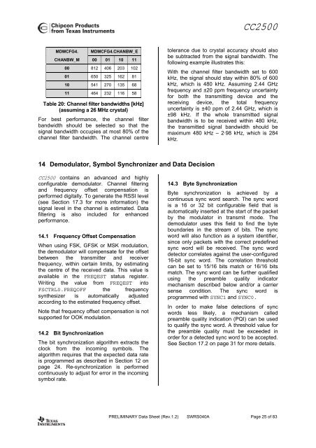
CC2500MDMCFG4.MDMCFG4.CHANBW_ECHANBW_M 00 01 10 1100 812 406 203 10201 650 325 162 8110 541 270 135 6811 464 232 116 58Table 20: Channel filter bandwidths [kHz](assuming a 26 MHz crystal)For best performance, the channel filterbandwidth should be selected so that thesignal bandwidth occupies at most 80% of thechannel filter bandwidth. The channel centretolerance due to crystal accuracy should alsobe subtracted from the signal bandwidth. Thefollowing example illustrates this:With the channel filter bandwidth set to 600kHz, the signal should stay within 80% of 600kHz, which is 480 kHz. Assuming 2.44 GHzfrequency and ±20 ppm frequency uncertaintyfor both the transmitting device and thereceiving device, the total frequencyuncertainty is ±40 ppm of 2.44 GHz, which is±98 kHz. If the whole transmitted signalbandwidth is to be received within 480 kHz,the transmitted signal bandwidth should bemaximum 480 kHz – 2·98 kHz, which is 284kHz.14 Demodulator, Symbol Synchronizer and Data DecisionCC2500 contains an advanced and highlyconfigurable demodulator. Channel filteringand frequency offset compensation isperformed digitally. To generate the RSSI level(see Section 17.3 for more information) thesignal level in the channel is estimated. Datafiltering is also included for enhancedperformance.14.1 Frequency Offset CompensationWhen using FSK, GFSK or MSK modulation,the demodulator will compensate for the offsetbetween the transmitter and receiverfrequency, within certain limits, by estimatingthe centre of the received data. This value isavailable in the FREQEST status register.Writing the value from FREQEST intoFSCTRL0.FREQOFF the frequencysynthesizer is automatically adjustedaccording to the estimated frequency offset.Note that frequency offset compensation is notsupported for OOK modulation.14.2 Bit SynchronizationThe bit synchronization algorithm extracts theclock from the incoming symbols. Thealgorithm requires that the expected data rateis programmed as described in Section 12 onpage 24. Re-synchronization is performedcontinuously to adjust for error in the incomingsymbol rate.14.3 Byte SynchronizationByte synchronization is achieved by acontinuous sync word search. The sync wordis a 16 or 32 bit configurable field that isautomatically inserted at the start of the packetby the modulator in transmit mode. Thedemodulator uses this field to find the byteboundaries in the stream of bits. The syncword will also function as a system identifier,since only packets with the correct predefinedsync word will be received. The sync worddetector correlates against the user-configured16-bit sync word. The correlation thresholdcan be set to 15/16 bits match or 16/16 bitsmatch. The sync word can be further qualifiedusing the preamble quality indicatormechanism described below and/or a carriersense condition. The sync word isprogrammed with SYNC1 and SYNC0.In order to make false detections of syncwords less likely, a mechanism calledpreamble quality indication (PQI) can be usedto qualify the sync word. A threshold value forthe preamble quality must be exceeded inorder for a detected sync word to be accepted.See Section 17.2 on page 31 for more details.PRELIMINARY Data Sheet (<strong>Rev</strong>.1.2) SWRS040A Page 25 of 83


![td-res-4 [Compatibility Mode]](https://img.yumpu.com/45826987/1/184x260/td-res-4-compatibility-mode.jpg?quality=85)