Single-Chip Low Cost Low Power RF-Transceiver (Rev. A)
Single-Chip Low Cost Low Power RF-Transceiver (Rev. A)
Single-Chip Low Cost Low Power RF-Transceiver (Rev. A)

Create successful ePaper yourself
Turn your PDF publications into a flip-book with our unique Google optimized e-Paper software.
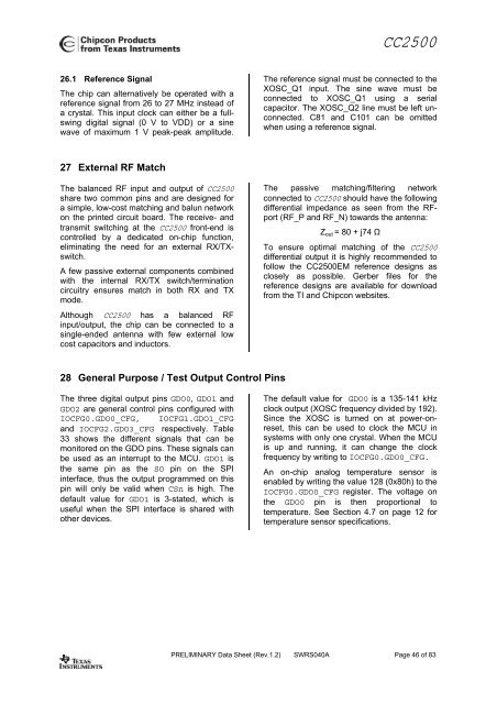
CC250026.1 Reference SignalThe chip can alternatively be operated with areference signal from 26 to 27 MHz instead ofa crystal. This input clock can either be a fullswingdigital signal (0 V to VDD) or a sinewave of maximum 1 V peak-peak amplitude.The reference signal must be connected to theXOSC_Q1 input. The sine wave must beconnected to XOSC_Q1 using a serialcapacitor. The XOSC_Q2 line must be left unconnected.C81 and C101 can be omittedwhen using a reference signal.27 External <strong>RF</strong> MatchThe balanced <strong>RF</strong> input and output of CC2500share two common pins and are designed fora simple, low-cost matching and balun networkon the printed circuit board. The receive- andtransmit switching at the CC2500 front-end iscontrolled by a dedicated on-chip function,eliminating the need for an external RX/TXswitch.A few passive external components combinedwith the internal RX/TX switch/terminationcircuitry ensures match in both RX and TXmode.Although CC2500 has a balanced <strong>RF</strong>input/output, the chip can be connected to asingle-ended antenna with few external lowcost capacitors and inductors.The passive matching/filtering networkconnected to CC2500 should have the followingdifferential impedance as seen from the <strong>RF</strong>port(<strong>RF</strong>_P and <strong>RF</strong>_N) towards the antenna:Z out = 80 + j74 ΩTo ensure optimal matching of the CC2500differential output it is highly recommended tofollow the CC2500EM reference designs asclosely as possible. Gerber files for thereference designs are available for downloadfrom the TI and <strong>Chip</strong>con websites.28 General Purpose / Test Output Control PinsThe three digital output pins GDO0, GDO1 andGDO2 are general control pins configured withIOCFG0.GDO0_CFG, IOCFG1.GDO1_CFGand IOCFG2.GDO3_CFG respectively. Table33 shows the different signals that can bemonitored on the GDO pins. These signals canbe used as an interrupt to the MCU. GDO1 isthe same pin as the SO pin on the SPIinterface, thus the output programmed on thispin will only be valid when CSn is high. Thedefault value for GDO1 is 3-stated, which isuseful when the SPI interface is shared withother devices.The default value for GDO0 is a 135-141 kHzclock output (XOSC frequency divided by 192).Since the XOSC is turned on at power-onreset,this can be used to clock the MCU insystems with only one crystal. When the MCUis up and running, it can change the clockfrequency by writing to IOCFG0.GDO0_CFG.An on-chip analog temperature sensor isenabled by writing the value 128 (0x80h) to theIOCFG0.GDO0_CFG register. The voltage onthe GDO0 pin is then proportional totemperature. See Section 4.7 on page 12 fortemperature sensor specifications.PRELIMINARY Data Sheet (<strong>Rev</strong>.1.2) SWRS040A Page 46 of 83

![td-res-4 [Compatibility Mode]](https://img.yumpu.com/45826987/1/184x260/td-res-4-compatibility-mode.jpg?quality=85)