Single-Chip Low Cost Low Power RF-Transceiver (Rev. A)
Single-Chip Low Cost Low Power RF-Transceiver (Rev. A)
Single-Chip Low Cost Low Power RF-Transceiver (Rev. A)

Create successful ePaper yourself
Turn your PDF publications into a flip-book with our unique Google optimized e-Paper software.
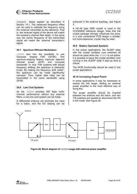
CC2500FREQEST status register as described inSection 14.1. The measured frequency offsetcan be used to calibrate the frequency usingthe ‘external’ transmitter as the reference. Thatis, the received signal of the device will matchthe receiver’s channel filter better. In the sameway the centre frequency of the transmittedsignal will match the ‘external’ transmitter’ssignal.30.7 Spectrum Efficient ModulationCC2500 also has the possibility to useGaussian shaped FSK (GFSK). Thisspectrum-shaping feature improves adjacentchannel power (ACP) and occupiedbandwidth. In ‘true’ FSK systems with abruptfrequency shifting, the spectrum is inherentlybroad. By making the frequency shift ‘softer’,the spectrum can be made significantlynarrower. Thus, higher data rates can betransmitted in the same bandwidth usingGFSK.30.8 <strong>Low</strong> <strong>Cost</strong> SystemsAs the CC2500 provides 500 kbps multichannelperformance without any externalfilters, a very low cost system can be made.A differential antenna will eliminate the needfor a balun, and the DC biasing can beachieved in the antenna topology, see Figure3.A HC-49 type SMD crystal is used in theCC2500EM reference design. Note that thecrystal package strongly influences the price.In a size constrained PCB design a smaller,but more expensive, crystal may be used.30.9 Battery Operated SystemsIn low power applications, the SLEEP statewith the crystal oscillator core switched offshould be used when the CC2500 is not active.It is possible to leave the crystal oscillator corerunning in the SLEEP state if start-up time iscritical.The WOR functionality should be used in lowpower applications.30.10 Increasing Output <strong>Power</strong>In some applications it may be necessary toextend the link range. Adding an externalpower amplifier is the most effective way ofdoing this.The power amplifier should be insertedbetween the antenna and the balun, and twoT/R switches are needed to disconnect the PAin RX mode. See Figure 28.AntennaFilterPABalunCC2500T/R switchT/R switchFigure 28. Block diagram of CC2500 usage with external power amplifierPRELIMINARY Data Sheet (<strong>Rev</strong>.1.2) SWRS040A Page 50 of 83

![td-res-4 [Compatibility Mode]](https://img.yumpu.com/45826987/1/184x260/td-res-4-compatibility-mode.jpg?quality=85)