Single-Chip Low Cost Low Power RF-Transceiver (Rev. A)
Single-Chip Low Cost Low Power RF-Transceiver (Rev. A)
Single-Chip Low Cost Low Power RF-Transceiver (Rev. A)

Create successful ePaper yourself
Turn your PDF publications into a flip-book with our unique Google optimized e-Paper software.
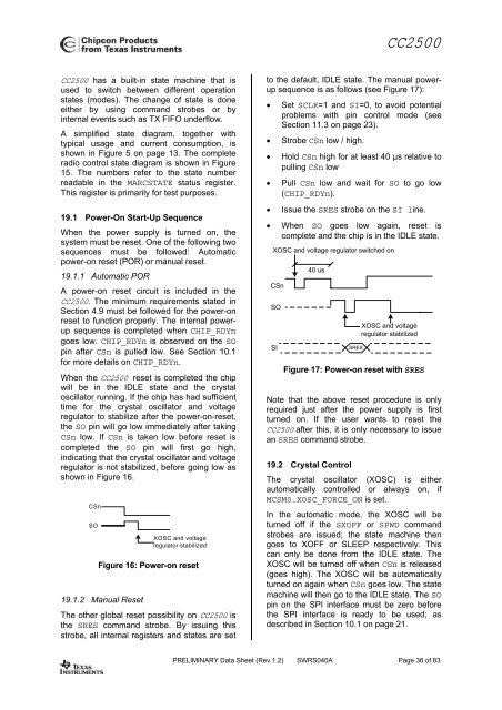
CC2500CC2500 has a built-in state machine that isused to switch between different operationstates (modes). The change of state is doneeither by using command strobes or byinternal events such as TX FIFO underflow.A simplified state diagram, together withtypical usage and current consumption, isshown in Figure 5 on page 13. The completeradio control state diagram is shown in Figure15. The numbers refer to the state numberreadable in the MARCSTATE status register.This register is primarily for test purposes.19.1 <strong>Power</strong>-On Start-Up SequenceWhen the power supply is turned on, thesystem must be reset. One of the following twosequences must be followed: Automaticpower-on reset (POR) or manual reset.19.1.1 Automatic PORA power-on reset circuit is included in theCC2500. The minimum requirements stated inSection 4.9 must be followed for the power-onreset to function properly. The internal powerupsequence is completed when CHIP_RDYngoes low. CHIP_RDYn is observed on the SOpin after CSn is pulled low. See Section 10.1for more details on CHIP_RDYn.When the CC2500 reset is completed the chipwill be in the IDLE state and the crystaloscillator running. If the chip has had sufficienttime for the crystal oscillator and voltageregulator to stabilize after the power-on-reset,the SO pin will go low immediately after takingCSn low. If CSn is taken low before reset iscompleted the SO pin will first go high,indicating that the crystal oscillator and voltageregulator is not stabilized, before going low asshown in Figure 16.CSnSOXOSC and voltageregulator stabilizedFigure 16: <strong>Power</strong>-on reset19.1.2 Manual ResetThe other global reset possibility on CC2500 isthe SRES command strobe. By issuing thisstrobe, all internal registers and states are setto the default, IDLE state. The manual powerupsequence is as follows (see Figure 17):• Set SCLK=1 and SI=0, to avoid potentialproblems with pin control mode (seeSection 11.3 on page 23).• Strobe CSn low / high.• Hold CSn high for at least 40 µs relative topulling CSn low• Pull CSn low and wait for SO to go low(CHIP_RDYn).• Issue the SRES strobe on the SI line.• When SO goes low again, reset iscomplete and the chip is in the IDLE state.XOSC and voltage regulator switched onCSnSOSI40 usSRESXOSC and voltageregulator stabilizedFigure 17: <strong>Power</strong>-on reset with SRESNote that the above reset procedure is onlyrequired just after the power supply is firstturned on. If the user wants to reset theCC2500 after this, it is only necessary to issuean SRES command strobe.19.2 Crystal ControlThe crystal oscillator (XOSC) is eitherautomatically controlled or always on, ifMCSM0.XOSC_FORCE_ON is set.In the automatic mode, the XOSC will beturned off if the SXOFF or SPWD commandstrobes are issued; the state machine thengoes to XOFF or SLEEP respectively. Thiscan only be done from the IDLE state. TheXOSC will be turned off when CSn is released(goes high). The XOSC will be automaticallyturned on again when CSn goes low. The statemachine will then go to the IDLE state. The SOpin on the SPI interface must be zero beforethe SPI interface is ready to be used; asdescribed in Section 10.1 on page 21.PRELIMINARY Data Sheet (<strong>Rev</strong>.1.2) SWRS040A Page 36 of 83

![td-res-4 [Compatibility Mode]](https://img.yumpu.com/45826987/1/184x260/td-res-4-compatibility-mode.jpg?quality=85)