Single-Chip Low Cost Low Power RF-Transceiver (Rev. A)
Single-Chip Low Cost Low Power RF-Transceiver (Rev. A)
Single-Chip Low Cost Low Power RF-Transceiver (Rev. A)

You also want an ePaper? Increase the reach of your titles
YUMPU automatically turns print PDFs into web optimized ePapers that Google loves.
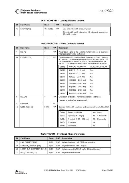
CC25000x1F: WOREVT0 – <strong>Low</strong> byte Event0 timeoutBit Field Name Reset R/W Description7:0 EVENT0[7:0] 107 (0x6B) R/W <strong>Low</strong> byte of Event 0 timeout register.The default Event 0 value gives 1.0 s timeout, assuming a26.0 MHz crystal.0x20: WORCTRL – Wake On Radio controlBit Field Name Reset R/W Description7 RC_PD 1 R/W <strong>Power</strong> down signal to RC oscillator. When written to 0, automaticinitial calibration will be performed6:4 EVENT1[2:0] 7 (111) R/W Timeout setting from register block. Decoded to Event 1 timeout.RC oscillator clock frequency equals F XOSC /750, which is 34.7-36kHz, depending on crystal frequency. The table below lists thenumber of clock periods after Event 0 before Event 1 times out.Setting WOR_AUTOSYNC=0 WOR_AUTOSYNC=10 (000) 4 (0.111 – 0.115 ms) NA1 (001) 6 (0.167 – 0.173 ms) NA2 (010) 8 (0.222 – 0.230 ms) NA3 (011) 12 (0.333 – 0.346 ms) NA4 (100) 16 (0.444 – 0.462 ms) NA5 (101) 24 (0.667 – 0.692 ms) NA6 (110) 32 (0.889 – 0.923 ms) NA7 (111) 48 (1.333 – 1.385 ms) NA3 RC_CAL 1 R/W Enables (1) or disables (0) the RC oscillator calibration.Included for debug/test purposes only.2 Reserved R01:0 WOR_RES[1:0] 0 (00) R/W Controls the Event 0 resolution and maximum timeout of the WORmodule:Setting Resolution (1 LSB) Max timeout0 (00) 1 period (28 – 29 µs) 1.8 – 1.9 seconds1 (01) 2 5 periods (0.89 – 0.92 ms) 58 – 61 seconds2 (10) Do not use NA3 (11) Do not use NA0x21: FREND1 – Front end RX configurationBit Field Name Reset R/W Description7:6 LNA_CURRENT[1:0] 1 (01) R/W Adjusts front-end LNA PTAT current output5:4 LNA2MIX_CURRENT[1:0] 1 (01) R/W Adjusts front-end PTAT outputs3:2 LODIV_BUF_CURRENT_RX[1:0] 1 (01) R/W Adjusts current in RX LO buffer (LO input to mixer)1:0 MIX_CURRENT[1:0] 2 (10) R/W Adjusts current in mixerPRELIMINARY Data Sheet (<strong>Rev</strong>.1.2) SWRS040A Page 72 of 83


![td-res-4 [Compatibility Mode]](https://img.yumpu.com/45826987/1/184x260/td-res-4-compatibility-mode.jpg?quality=85)