Single-Chip Low Cost Low Power RF-Transceiver (Rev. A)
Single-Chip Low Cost Low Power RF-Transceiver (Rev. A)
Single-Chip Low Cost Low Power RF-Transceiver (Rev. A)

You also want an ePaper? Increase the reach of your titles
YUMPU automatically turns print PDFs into web optimized ePapers that Google loves.
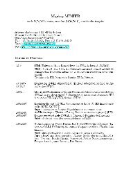
CC25000x18: MCSM0 – Main Radio Control State Machine configurationBit Field Name Reset R/W Description7:6 Reserved R05:4 FS_AUTOCAL[1:0] 0 (00) R/W Automatically calibrate when going to RX or TX, or back to IDLESettingWhen to perform automatic calibration0 (00) Never (manually calibrate using SCAL strobe)1 (01) When going from IDLE to RX or TX (or FSTXON)2 (10) When going from RX or TX back to IDLE3 (11) Every 4 th time when going from RX or TX to IDLEIn some automatic wake-on-radio (WOR) applications, usingsetting 3 (11) can significantly reduce current consumption.3:2 PO_TIMEOUT 1 (01) R/W Programs the number of times the six-bit ripple counter mustexpire after XOSC has stabilized before CHP_RDYn goes low.If XOSC is on (stable) during power-down, PO_TIMEOUTshould be set so that the regulated digital supply voltage hastime to stabilize before CHIP_RDYn goes low (PO_TIMEOUT =2 recommended).If XOSC is off during power-down, the regulated digital supplyvoltage has time to stabilize while waiting for the crystal to bestable and PO_TIMEOUT can be set to 0.Setting Expire count Timeout after XOSC start0 (00) 1 Approx. 2.3 – 2.4 µs1 (01) 16 Approx. 37 – 39 µs2 (10) 64 Approx. 149 – 155 µs3 (11) 256 Approx. 597 – 620 µsExact timeout depends on crystal frequency.1 PIN_CTRL_EN 0 R/W Enables the pin radio control option0 XOSC_FORCE_ON 0 R/W Force the XOSC to stay on in the SLEEP state.PRELIMINARY Data Sheet (<strong>Rev</strong>.1.2) SWRS040A Page 66 of 83


![td-res-4 [Compatibility Mode]](https://img.yumpu.com/45826987/1/184x260/td-res-4-compatibility-mode.jpg?quality=85)