Single-Chip Low Cost Low Power RF-Transceiver (Rev. A)
Single-Chip Low Cost Low Power RF-Transceiver (Rev. A)
Single-Chip Low Cost Low Power RF-Transceiver (Rev. A)

Create successful ePaper yourself
Turn your PDF publications into a flip-book with our unique Google optimized e-Paper software.
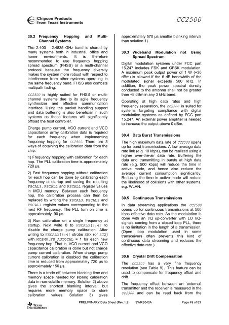
CC250030.2 Frequency Hopping and Multi-Channel SystemsThe 2.400 – 2.4835 GHz band is shared bymany systems both in industrial, office andhome environments. It is thereforerecommended to use frequency hoppingspread spectrum (FHSS) or a multi-channelprotocol because the frequency diversitymakes the system more robust with respect tointerference from other systems operating inthe same frequency band. FHSS also combatsmultipath fading.CC2500 is highly suited for FHSS or multichannelsystems due to its agile frequencysynthesizer and effective communicationinterface. Using the packet handling supportand data buffering is also beneficial in suchsystems as these features will significantlyoffload the host controller.Charge pump current, VCO current and VCOcapacitance array calibration data is requiredfor each frequency when implementingfrequency hopping for CC2500. There are 3ways of obtaining the calibration data from thechip:1) Frequency hopping with calibration for eachhop. The PLL calibration time is approximately720 µs.2) Fast frequency hopping without calibrationfor each hop can be done by calibrating eachfrequency at startup and saving the resultingFSCAL3, FSCAL2 and FSCAL1 register valuesin MCU memory. Between each frequencyhop, the calibration process can then bereplaced by writing the FSCAL3, FSCAL2 andFSCAL1 register values corresponding to thenext <strong>RF</strong> frequency. The PLL turn on time isapproximately 90 µs.3) Run calibration on a single frequency atstartup. Next write 0 to FSCAL3[5:4] todisable the charge pump calibration. Afterwriting to FSCAL3[5:4] strobe SRX (or STX)with MCSM0.FS_AUTOCAL = 1 for each newfrequency hop. That is, VCO current and VCOcapacitance calibration is done but not chargepump current calibration. When charge pumpcurrent calibration is disabled the calibrationtime is reduced from approximately 720 µs toapproximately 150 µs.There is a trade off between blanking time andmemory space needed for storing calibrationdata in non-volatile memory. Solution 2) abovegives the shortest blanking interval, butrequires more memory space to storecalibration values. Solution 3) givesapproximately 570 µs smaller blanking intervalthan solution 1).30.3 Wideband Modulation not UsingSpread SpectrumDigital modulation systems under FCC part15.247 includes FSK and GFSK modulation.A maximum peak output power of 1 W (+30dBm) is allowed if the 6 dB bandwidth of themodulated signal exceeds 500 kHz. Inaddition, the peak power spectral densityconducted to the antenna shall not be greaterthan +8 dBm in any 3 kHz band.Operating at high data rates and highfrequency separation, the CC2500 is suited forsystems targeting compliance with digitalmodulation systems as defined by FCC part15.247. An external power amplifier is neededto increase the output above 0 dBm.30.4 Data Burst TransmissionsThe high maximum data rate of CC2500 opensup for burst transmissions. A low average datarate link (e.g. 10 kbps), can be realized using ahigher over-the-air data rate. Buffering thedata and transmitting in bursts at high datarate (e.g. 500 kbps) will reduce the time inactive mode, and hence also reduce theaverage current consumption significantly.Reducing the time in active mode will reducethe likelihood of collisions with other systems,e.g. WLAN.30.5 Continuous TransmissionsIn data streaming applications the CC2500opens up for continuous transmissions at 500kbps effective data rate. As the modulation isdone with an I/Q up-converter with LO I/Qsignalscoming from a closed loop PLL, thereis no limitation in the length of a transmission.(Open loop modulation used in sometransceivers often prevents this kind ofcontinuous data streaming and reduces theeffective data rate.)30.6 Crystal Drift CompensationThe CC2500 has a very fine frequencyresolution (see Table 9). This feature can beused to compensate for frequency offset anddrift.The frequency offset between an ‘external’transmitter and the receiver is measured in theCC2500 and can be read back from thePRELIMINARY Data Sheet (<strong>Rev</strong>.1.2) SWRS040A Page 49 of 83

![td-res-4 [Compatibility Mode]](https://img.yumpu.com/45826987/1/184x260/td-res-4-compatibility-mode.jpg?quality=85)