Kingscote Airport Business Case Appendices - Kangaroo Island ...
Kingscote Airport Business Case Appendices - Kangaroo Island ...
Kingscote Airport Business Case Appendices - Kangaroo Island ...
- No tags were found...

Create successful ePaper yourself
Turn your PDF publications into a flip-book with our unique Google optimized e-Paper software.
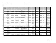
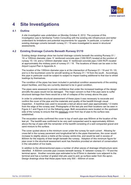
4 Site Investigations4.1 OutlineA site investigation was undertaken on Monday October 8, 2012. The purpose of thisinvestigation was to familiarise Tonkin Consulting with the existing site infrastructure and betterunderstand its limitations and potential requirements for upgrade. In particular, a number ofexisting drainage culverts beneath runway 01 / 19 were investigated to assist in structuralassessments.4.2 Existing Drainage Culverts Beneath Runway 01/19Existing design drawings show two buried drainage culverts beneath the existing Runway 01 /19; a 1350mm diameter class ‘X’ reinforced concrete pipe (1350 RCP) located at the junction ofrunway 15 / 33; and a 1200mm diameter class ‘X’ reinforced concrete pipe (1200 RCP) locatedat approximately the midway point of runway 01 / 19. The locations of these can be seen in the<strong>Airport</strong> Layout Plan in Appendix A.The location of the 1350mm diameter pipe is at the intersection of Runways 01 / 19 and 15 / 33,and is in the touchdown zone for aircraft landing on Runway 01 / 19 from the south. Accordingly,this pipe in particular could be subject to subject to impact loading additional to that due to wheelloadings by themselves.The condition of the pipes has been included in periodical condition assessments of the existingairport facilities, and they are currently deemed to be in good condition.The pipes were assessed to provide confidence that under the increased loadings of the designaircrafts the pipes would not be damaged. The major concern is that if the pipe were to sufferstructural damage then there would be a risk of collapse of the runway above the pipe.In order to undertake structural assessment of these pipes it was necessary to excavate andconfirm the cover of the pipe and the materials and quality of the backfill through visualinspection. A backhoe was used to excavate a test pit above each pipe approximately 1.0 metrefrom the edge of the runway seal. Photographs of the test pits and their locations can be seen inFigure 4-1 and Figure 4-2 on the following page. Both excavations were located on the upstreamside of the runway to ensure that the minimum cover from top of pipe to the surface wasestablished.The excavation works confirmed the cover to top of each pipe was 800mm at the location of thetest pit. The backfill was confirmed to be very well compacted sand to approximately 400mmabove the top of pipe with the remainder of the backfill consisting of a well compacted gravel andsand mixture to the surface.The cover quoted above is the minimum cover under the runway for each culvert. Allowing forcross-fall in the runway pavement and longitudinal fall in the pipes themselves, the cover wouldincrease to slightly above a metre at the runway centre-line, and would be well in excess of800mm for the majority of their length beneath the runway. Adoption of this minimum figure forpipe cover in the structural assessment work has therefore provided an element of conservatismin the calculation of live loads.In addition to the aforementioned pipes a number of other pieces of drainage infrastructure wereidentified. A 600mm concrete pipe crosses beneath taxiway ‘A’ between runway 01 / 19 and theterminal apron. Another concrete pipe estimated to be 675mm in diameter runs adjacent to theterminal and has a number of grated inlet pits used to pick up surface water from the apron.Design drawings show that these pipes have only 500 – 600mm of cover.Ref No. 20120935DR1A <strong>Kingscote</strong> <strong>Airport</strong> Infrastructure Study Report 5