Untitled - Uhlenbrock
Untitled - Uhlenbrock
Untitled - Uhlenbrock

Create successful ePaper yourself
Turn your PDF publications into a flip-book with our unique Google optimized e-Paper software.
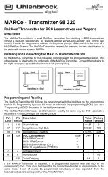
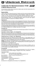
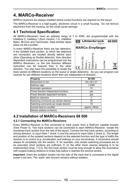
4. MARCo-ReceiverMARCoMARCo receivers are always installed where control functions are required on the layout.The MARCo-Receiver is a high-quality, electronic circuit in a small housing. Do not removeelectronics from the housing, as this could cause damage.4.1 Technical SpecificationAll MARCo-Receivers have an address range of 1 to 4095, are programmable with theIntellibox II, Intellibox I (from Version 1.3), IntelliboxBasic, IB-Com and TwinCenter. Data transfer takesplace via the LocoNet.In every MARCo-Receiver there are two detectors.If the isolated track section, to which the detectorsare connected, are located directly behind eachother (Operating as Double detector), then directiondependent instructions can be programmed into theMARCo Receivers, i.e. the one direction differentinstruction can be execute than in the otherdirection. You also have the possibility to locate thetrack section at different locations on the layout (2 single detectors). So you can program onereceiver for two different locations which then are independent of direction.Property 68 500Dimensions in mm 53 x 50 x 21Address rage 1-4095Automatic operations 12Travel direction independent functionsyesTravel direction dependent functionsyesRailCom detectors 2Switching commands per double detector 30Switching commands per single detector 15Current load on LocoNetapprox. 25mAModule address ex-factory 14.2 Installation of MARCo-Receivers 68 5004.2.1 Connecting the MARCo-ReceiversEvery MARCo-Receiver is first connected to track power from a RailCom capable booster(here Power 4). Two track sections can be connected to each MARCo-Receiver. Isolate themonitored track section from the rest of the layout. Connect the first track section, according todriving direction, to input Gleis 1 (track 1) and the second to input Gleis 2 (track 2). The lengthand position of the isolated sections depend on the selected function and the type of traffic thereceiver is to control (e.g. acceleration and braking) on your locomotives. A locomotive shouldalways fit completely into the section. If, for example, only simple switching processes are tobe executed, short sections are sufficient. If, on the other hand, precise stopping is to beimplemented (chap. 7.5.2), the first track section must be long enough to allow the locomotivewith longest braking distance to brake fully before it reaches the second section.Important: Insert the isolation breaks into the side of the track that is connected to the digitalpower’s red wire. The ‘earth’ wire (brown) remains without isolation.13