Untitled - Uhlenbrock
Untitled - Uhlenbrock
Untitled - Uhlenbrock

You also want an ePaper? Increase the reach of your titles
YUMPU automatically turns print PDFs into web optimized ePapers that Google loves.
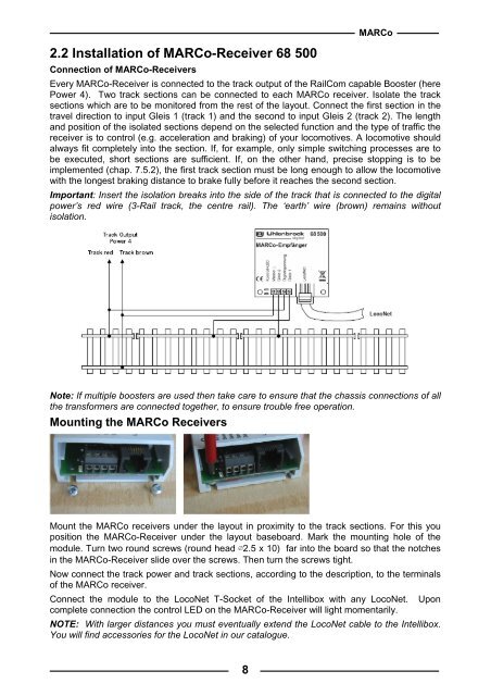
2.2 Installation of MARCo-Receiver 68 500MARCoConnection of MARCo-ReceiversEvery MARCo-Receiver is connected to the track output of the RailCom capable Booster (herePower 4). Two track sections can be connected to each MARCo receiver. Isolate the tracksections which are to be monitored from the rest of the layout. Connect the first section in thetravel direction to input Gleis 1 (track 1) and the second to input Gleis 2 (track 2). The lengthand position of the isolated sections depend on the selected function and the type of traffic thereceiver is to control (e.g. acceleration and braking) of your locomotives. A locomotive shouldalways fit completely into the section. If, for example, only simple switching processes are tobe executed, short sections are sufficient. If, on the other hand, precise stopping is to beimplemented (chap. 7.5.2), the first track section must be long enough to allow the locomotivewith the longest braking distance to brake fully before it reaches the second section.Important: Insert the isolation breaks into the side of the track that is connected to the digitalpower’s red wire (3-Rail track, the centre rail). The ‘earth’ wire (brown) remains withoutisolation.Note: If multiple boosters are used then take care to ensure that the chassis connections of allthe transformers are connected together, to ensure trouble free operation.Mounting the MARCo ReceiversMount the MARCo receivers under the layout in proximity to the track sections. For this youposition the MARCo-Receiver under the layout baseboard. Mark the mounting hole of themodule. Turn two round screws (round head ∅2.5 x 10) far into the board so that the notchesin the MARCo-Receiver slide over the screws. Then turn the screws tight.Now connect the track power and track sections, according to the description, to the terminalsof the MARCo receiver.Connect the module to the LocoNet T-Socket of the Intellibox with any LocoNet. Uponcomplete connection the control LED on the MARCo-Receiver will light momentarily.NOTE: With larger distances you must eventually extend the LocoNet cable to the Intellibox.You will find accessories for the LocoNet in our catalogue.8