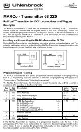
MARCoA.1 MARCO transmitter 68320 Configuration Variable (CVs)CVs CVsValue FactoryMeaningLoco MARCORange default1 116 Short address 0-127 317 117 Long address High byte 192-231 19918 118 Long address Low byte 0-255 208short address valid29 1290-32 0long address validA.2 LNCV Table for the MARCo ReceiverLNCV Description0 Module address and first detector addressGeneral address : 655351 Address track 2 (2. Single detector) for track 2, or as feedback address(according to Module configuration in LNCV 15)2 Selection of the different modesBasic functions0 = Receiving locomotive data via a double detector.Transmission of address, category, driving direction and speed.Note: Transmission on the LocoNet is activated with LNCV 15.1 = Receiving locomotive data over 2 single detectors in 2independent places on the Layout.Note: Transmission on the LocoNet is activated with LNCV 15.Switching operation2 = Switching operations with double detector in a single location onthe layout with direction sensing3 = Switching operations with 2 single detectors at 2 indepententlocations on the layout with direction detectionAutomatic functions without block reporting4 = time controlled shuttle traffic terminus5 = signal controlled shuttle traffic terminus6 = time controlled holding point7 = block section/station block8 = entry manager9 = exit manager, chronological track sequence10 = exit manager, random track sequence11 = exit manager, chronological track sequence, selective trackswitching12 = Exit manager, random track sequence, selective track switchingAutomatic functions with block reporting20 = time controlled shuttle traffic terminus with block status message21 = signal controlled shuttle traffic terminus with block status message22 = time controlled holding point with block status message23 = block section/station block with block status message24 = entry manager with block status message25 = exit managers, chron. track sequence with block status message26 = exit managers, random track sequence with block status message27 = exit manager, chronological track sequence, selective trackswitching28 = exit manager, random track sequenceDelete functions96 = delete current operating status.Programmed LNCVs are not changed.97 = delete all LNCVs starting from LNCV 2098 = all LNCVs sets 0, except LNCV 0 and 1 (address) to the value99 = restore factory defaults, without address changeValue SeeRange chapter1-4095 5.1655351-4095 5.1, B20-10,2,34-1220-2896-995.2And7.78
MARCoLNCV Description3 Direction in which the automation is active according to LNCV 20 = Automatic active with travel direction from track 1 to track 21 = Automatic active with travel direction from track 2 to track 12 = Automatic active in both travel directions (only stopping point)4 Holding time for shuttle traffic and terminus (automatic functions in setin LNCV 2). Value in seconds.5 Delay period between switching the locomotive’s route and thedeparture of the waiting locomotive applies to all modes set in LNCV 2.Value in seconds.6 Solenoid address of the exit signal for the automatic mode set in LNCV2. In automatic modes 4, 6, 20 and 22 the signal is set by the module;in automatic modes 5, 7-10, 21 and 23-26 the signal is monitoredstopping the train.Note: This signal must always be specified in automatic mode.7 1. Address for solenoid, routes from Intellibox or feedback for thoseAutomatic modes set in LNCV 2. The appropriate instruction is sent, ifthe detector is passed.0 = no address instruction is sent20010 - 20241 = switch an Intellibox route10, 20, 30 - 20000 = solenoid 1, 2, 3 - 2000 set to red/round11, 21, 31 - 20001 = solenoid 1, 2, 3 - 2000 to green/straight set12, 22, 32 - 20482 = feedback address 1, 2, 3 - 2048 - vacant13, 23, 33 - 20483 = feedback address 1, 2, 3 - 2048 - occupied20010-20241 = Intellibox I – Route switching8 2. Address for solenoid, routes in Intellibox or feedback for thoseautomatic mode as set in LNCV 2. See LNCV 7.9 Block speedIf a speed step (2-127) is entered here, then the module in theautomatic modes 4-10 and 20-26 (LNCV 2) can use a 3 detectorsystem. The normal double detector detects the train and reduces itsspeed to the specified value. Detector 2 and 3 are connected inparallel - 2. Detector 3. then brakes the train to speed step 1 (=emergency stop).0 = stop with the locomotive decoder’s-internal delay1 = emergency stop (stop without delay)2-127 = speed step for the slow section10 Block option = options for reporting the change in block status from"occupied" to "vacant", if a train drives out of or through the block.0 = exit signal (LNCV 6) is set to "red" after the block is vacated1-255 = the statue is reported after the specified Value in seconds.257-511 = like previously. Now the Exit signal in LNCV 6 is set to red.Value in seconds + 25611 Automatic operation functions by solenoid address switch on or off.0 = no mechanism influence by the solenoid address1-2000 = solenoid red: MARCo-Receiver is not active or green isactivate12 Train dependent automation = switching automatic functions on or offby train categories.For functions 4-12 and 20-28 as in LNCV 20 = no automatic influence by train categories1-15 = All train categories the except the one entered should influencethe automatic function upon arrival in the track section,101-115 = Only the one entered should influence the automaticfunction upon arrival in the track section.Value SeeRange chapter0-2 7.40-255 7.4.17.4.30-255 7.4.51 2000 7.4.17.4.40-20483 7.4.17.4.50-20483 7.4.17.4.50-127 7.4.20-511 7.4.50-2000 7.4.30-15101-1157.4.479